Recommended resources
The freely available resources this lesson will direct you to.
Hello! Welcome to the third lesson in our module on ideal sources.
In the last lesson, we established the core behavior of ideal voltage and current sources. You learned that an ideal voltage source is a "voltage enforcer," maintaining a constant voltage regardless of the current, which gives it a vertical I-V characteristic.
Today, we will build directly on that foundation. Our goal is to reason about the physical result of combining voltage sources in series versus parallel, including why certain configurations are invalid. This is a crucial step towards analyzing more complex, realistic circuits where multiple sources might be present. Your interest in puzzles and logical thinking will be particularly useful as we explore why some connections are perfectly valid while others create a logical contradiction.
The Hydraulic Analogy Revisited
To build our intuition, let's start with the hydraulic analogy we've touched on before. Voltage is like water pressure, and current is like water flow. A battery or voltage source is like a water pump.
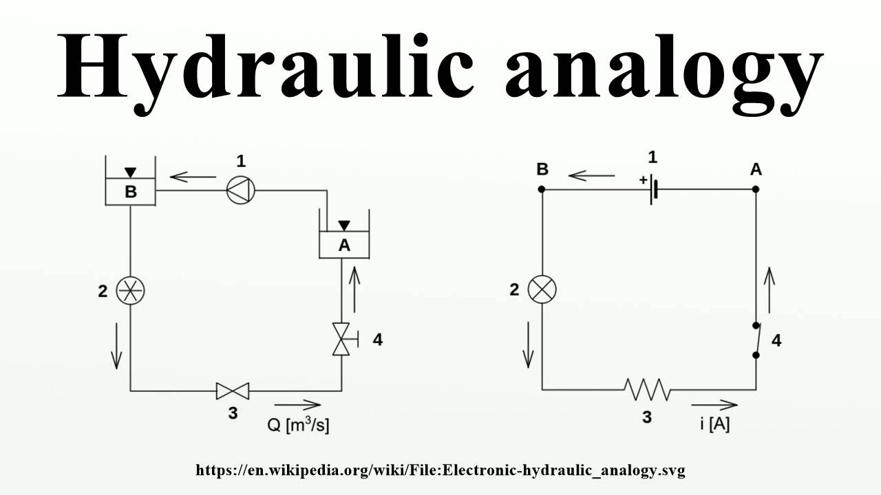
Imagine you have a task that requires more pressure than a single pump can provide. What do you do? You connect two pumps in series, one after the other, so their pressures add up. Conversely, if you need to supply a greater volume of water than one pump can handle, you might connect them in parallel to share the load.
This simple, physical intuition is almost a perfect match for how voltage sources behave.
1. Voltage Sources in Series: Stacking Potential
When we connect voltage sources in series, we are essentially "stacking" their ability to do work on charges. Each source gives an energy "boost" to the charges passing through it.
A great way to think about this comes from a forum on Electronics Stack Exchange, which you might find interesting for deeper dives. One answer explains that for an electron to travel through a circuit with two batteries in series, it must undergo two chemical reactions (one in each battery). This means the total work done on that single electron is doubled, and since voltage is work per unit charge (), the total voltage is doubled. The potential energies add up.
Let's watch a video that uses a similar analogy based on gravitational potential energy.
Sources in Series and Parallel (Circuits for Beginners #10)
The video 'Sources in Series and Parallel' by Aaron Danner provides an excellent intuitive start using a gravitational analogy. It also includes a practical demonstration.
Please watch from the beginning to 02:24. Notice how climbing two hills in a row is analogous to a charge passing through two voltage sources in series. The heights add, just like the voltages add. Then, see this confirmed with a real-world measurement of two batteries.
There are two ways to connect sources in series:
Series-Aiding Configuration
This is the standard connection you see in many devices, like a TV remote. The positive terminal of one source is connected to the negative terminal of the next. Their individual conventional current directions align, so they "aid" each other.
The total voltage is the sum of the individual voltages:
Voltage Sources in Series Circuits (Full Lecture)
For a more detailed look at the application of series-aiding sources, let's watch 'Voltage Sources in Series Circuits' by Jim Pytel. He demonstrates how this is used to get more power.
Watch from 01:04 to 03:48. Pay attention to how stacking two 12V batteries provides 24V to a motor, resulting in a four-fold power increase. The examples of car batteries and solar panels are also great illustrations of this principle in action.
Series-Opposing Configuration
What if we flip one of the sources around, connecting positive to positive or negative to negative? Now the sources are working against each other. The stronger source will "win," and the net voltage will be the difference between them.
The total voltage is the absolute difference of the individual voltages:
The polarity of the combined source will match the polarity of the stronger individual source.
At first glance, this seems impractical. Why use two sources to get a lower voltage? However, this configuration is fundamental to understanding a very common process: battery charging.
Voltage Sources in Series Circuits (Full Lecture)
Let's return to the video from Jim Pytel. He provides an excellent explanation of battery charging as a practical, and important, use of a series-opposing setup.
Watch from 03:48 to 10:38. This is a longer segment, but it's packed with the kind of deep, conceptual insight you appreciate. Focus on these key ideas: The charger (e.g., 14V) and the battery being charged (e.g., 10V) are in opposition. The voltage difference (14V - 10V = 4V) is what drives the charging current. A current-limiting resistor is crucial to prevent a massive, damaging surge of current. As the battery charges, its voltage rises, the voltage difference shrinks, and the charging current naturally decreases.
This charging example is a perfect illustration of how abstract circuit rules have very real, physical consequences.
2. Voltage Sources in Parallel: Sharing the Load
Connecting elements in parallel means their terminals are connected to the same two points (nodes) in a circuit. A fundamental rule of circuits is that all elements in parallel must have the same voltage across them.
This immediately leads to two distinct cases for voltage sources.
Case 1: Parallel Sources with Equal Voltage
If we connect two ideal 10V sources in parallel, what is the resulting voltage? Since they are in parallel, the voltage across the combination must be 10V.
So, why would you do this? The answer lies in moving from the ideal world to the real world. Real sources have a limit to how much current they can supply. By placing two identical sources in parallel, they can share the current demand from the load.
Sources in Series and Parallel (Circuits for Beginners #10)
The video by Aaron Danner explains this concept of current sharing very clearly.
Watch from 02:24 to 04:27. The example shows that to deliver 1 Amp to a load, a single source must provide all 1A. But with two parallel sources, each one only needs to provide 0.5A. They work half as hard.
Case 2: Parallel Sources with Unequal Voltage (An Invalid Configuration)
This is where your interest in logical puzzles comes in. What happens if we try to connect a 10V ideal source in parallel with a 6V ideal source?
- The 10V source enforces 10V across the two connection points.
- The 6V source enforces 6V across the same two connection points.
This is a mathematical contradiction. A single pair of nodes cannot have two different potential differences at the same time. In the world of ideal circuit theory, this connection is forbidden. It violates the fundamental definition of a voltage source.
Sources in Series and Parallel (Circuits for Beginners #10)
Let's see this explained visually.
Watch the segment from 04:27 to 06:02. The key takeaway is the phrase 'mathematical impossibility.' You've defined the same two points as having two different voltages, which can't be.
To solidify this, here's a quick reading that summarizes the rules we've covered.
Voltage Source as Independent and Dependent Sources
The article 'Voltage Source as Independent and Dependent Sources' from Electronics-Tutorials.ws provides a concise summary of these rules. Pay attention to the section on 'Badly Connected Voltage Sources'.
Please read the sections titled 'Voltage Source in Parallel' and 'Voltage Source in Series'. Notice how the text explicitly states that connecting unequal ideal sources in parallel is 'not allowed'. This reinforces the concept of an invalid configuration.
What Happens in the Real World?
The "invalid" label applies to our ideal models. But what happens if you actually try this with two real batteries? As we saw in the charging example, the higher voltage source will try to force current into the lower voltage source.
Sources in Series and Parallel (Circuits for Beginners #10)
The final segment of the Danner video demonstrates exactly this real-world scenario.
Watch from 06:02 to the end. Observe how current flows from the stronger battery to the weaker one. This is why putting a new battery in parallel with an old one is a bad idea—you're just draining the new battery to charge the old one, often with damaging results.
This distinction is critical:
- Ideal Model: Connecting unequal voltage sources in parallel is a logical impossibility.
- Real World: Connecting unequal batteries in parallel creates a circuit where a large current can flow between them, leading to energy waste and potential damage.
Conclusion
Today, we've explored how voltage sources combine, using physical intuition as our guide.
Key Takeaways:
- Series-Aiding: Voltages add (). This is used to achieve a higher total voltage.
- Series-Opposing: Voltages subtract (). This is key to understanding processes like battery charging.
- Parallel (Equal Voltage): The voltage remains the same, but the sources share the current load, increasing the total current capacity.
- Parallel (Unequal Voltage): This configuration is invalid for ideal sources as it creates a mathematical contradiction. For real sources, it's a dangerous or wasteful setup where the stronger source dumps current into the weaker one.
Preview of the Next Lesson:
We've now mastered the rules for combining voltage sources. In the next lesson, we will turn our attention to their counterparts: current sources. We will explore what happens when we connect them in series and parallel, and you will discover an elegant "duality" in the rules compared to what we learned today.