Recommended resources
The freely available resources this lesson will direct you to.
- Engineering Statics Virtual Work Problems (Chapter 11 Hibbeler) | Engineers Academywww.youtube.com
- Virtual Work Method Lec 3 ||(Problem 1)|Engineering Mechanics|First Year Coursewww.youtube.com
- CE 102: Engineering Mechanicswww.civil.iitb.ac.in
- 2006-823: learning the virtual work method in staticspeer.asee.org
Hello Shiva, welcome to the first lesson in your tailored course on Engineering Mechanics, Strength of Materials, and Structural Analysis. We're starting with a powerful tool that's a high-yield topic for the UPSC exam: the Principle of Virtual Work.
This lesson will equip you to solve equilibrium problems for complex, interconnected systems like linkages and mechanisms. The primary advantage of this method, which you'll find particularly efficient, is its ability to solve for a single unknown force or moment directly, often bypassing the need to calculate all intermediate support reactions. This makes it a faster alternative to traditional static equilibrium equations in many cases.
We will cover the core concept, establish a systematic problem-solving procedure, and work through examples to solidify your understanding.
1. The Principle of Virtual Work (PVW)
At its core, the Principle of Virtual Work states that for a system of connected rigid bodies to be in equilibrium, the total virtual work done by all external active forces during any virtual displacement is zero.
Let's break down these terms:
- Virtual Displacement (): This is a hypothetical, infinitesimal (first-order differential) displacement that is consistent with the system's constraints. For example, a point on a slider can only have a virtual displacement along its track; a link pinned at one end can only have a virtual rotation about that pin. It's an imaginary movement we impose on the system.
- Virtual Work (): This is the work done by a force during a virtual displacement. For a force and displacement , the virtual work is . For a moment and virtual rotation , it's . Work is positive if the force/moment acts in the same direction as the displacement/rotation, and negative if they are opposed.
- Active Forces: These are the forces that do work during the virtual displacement. They are typically the external applied loads and moments.
Crucially, many forces in a system do no work. These include:
- Internal forces holding a rigid body together.
- Forces at frictionless pins connecting two links (due to Newton's third law, they cancel out).
- Reaction forces at fixed, frictionless pivots (as there is no displacement).
- Normal forces at frictionless surfaces when the displacement is tangent to the surface.
This is the key to the method's power: by choosing a virtual displacement, we can make the work done by many unknown reactions equal to zero, simplifying the problem immensely.
For a deeper dive into these foundational concepts, please review the following notes from an IIT Bombay course.
These notes concisely define the principle and, importantly, list the types of forces that do no work. This is the conceptual foundation we will build upon.
Please read the first page, focusing on the definitions of Work of a Force, Work of a Couple, and the Principle of Virtual Work. Pay close attention to the list under the heading Forces which do no work, as this is fundamental to applying the method efficiently. Also, note the distinction between active forces and reactive/internal forces.
2. A Systematic Approach to Problem-Solving
Solving problems with PVW follows a consistent, three-step process. This structured approach is key to avoiding errors, especially with signs and geometry.
-
Draw the Active Force Diagram: This is similar to a Free-Body Diagram (FBD), but you only need to show the external active forces and moments—those that will do work during the displacement. You can often ignore the reactions at pins and supports you aren't interested in.
-
Define Kinematics & Draw a Virtual Displacement Diagram (VDD):
- Identify the system's single degree of freedom (for most statics problems) and choose a single virtual displacement variable, like a small rotation .
- Sketch the system in its displaced configuration. This is your VDD.
- Using geometry and trigonometry, express the virtual displacement of every point where an active force is applied in terms of your chosen variable (). This usually involves writing the position coordinates of the points of application in terms of an angle , and then differentiating. For a position , the virtual displacement is .
-
Write and Solve the Virtual Work Equation:
- State the principle: .
- Sum the virtual work done by each active force: .
- Be meticulous with signs. If the force and its corresponding virtual displacement are in the same direction, the work is positive. If they are in opposite directions, the work is negative.
- Substitute the expressions for the virtual displacements from Step 2. The common term () will cancel out, leaving you with an equilibrium equation that you can solve for the unknown.
This methodical process is discussed in detail in the following paper.
2006-823: learning the virtual work method in statics
This paper provides an excellent, clear summary of the problem-solving strategy. It also offers a useful side-by-side comparison with the traditional equilibrium method.
Please read the section "IV. Learning the Virtual Work Method: Examples". Focus on the three major steps and one strategy outlined at the beginning of the section. Then, quickly review Example 1 to see how these steps are applied to a simple beam problem.
3. Application to Linkage Systems
Now let's see this method in action on a typical linkage problem, which is a common application in exams.
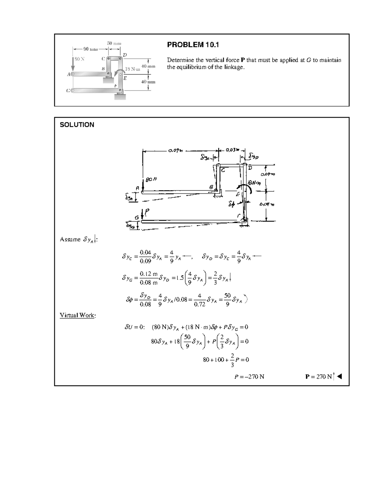
Let's break down the solution shown in the image:
-
Active Forces: The active forces are the 80 N force, the 18 N·m couple, and the unknown force P. The reactions at the pins are internal and do no net work.
-
Kinematics (Virtual Displacements): The key is to relate all displacements to a single variable. The solution chooses as the independent virtual displacement.
- Geometry: Using similar triangles and the geometry of the links, relationships are established. For example, looking at the vertical member BC, the rotation can be related to the horizontal movements at its ends. The solution jumps right to the final relationships, but they derive from the system's geometry.
- (from the lever arm BG)
- . Substituting , you get .
- .
- This is the most critical step. You must be comfortable with using geometry to find these kinematic relationships.
- Geometry: Using similar triangles and the geometry of the links, relationships are established. For example, looking at the vertical member BC, the rotation can be related to the horizontal movements at its ends. The solution jumps right to the final relationships, but they derive from the system's geometry.
-
Virtual Work Equation:
- Work of 80 N force: (Force is down, let's assume displacement is down, so positive work).
- Work of 18 N·m couple: .
- Work of force P: (Force P is up, but displacement is down, hence negative work).
- The solution shown seems to have a different sign convention where P is assumed to be in the same direction as the displacement. Let's follow a consistent rule: if force and displacement components are in the same direction, work is positive.
- Let's assume an upward virtual displacement . Then P does positive work, and the 80N force does negative work.
- (Assuming clockwise is negative)
- Substituting the kinematic relations:
(Note: the provided solution's signs imply all forces/moments are contributing to the same direction of work). Let's follow the image's equation: .
- Dividing by :
- Self-correction: The provided solution has different numerical relationships. . This seems to imply a different geometric constraint. The key takeaway is the method, not the specific numbers in this slightly unclear example. The process remains: Force × Virtual Displacement = Virtual Work. Sum to zero.
4. Video Walkthroughs
Watching experts solve problems is one of the best ways to learn the nuances. The following videos walk through two different linkage problems step-by-step.
Engineering Statics Virtual Work Problems (Chapter 11 Hibbeler) | Engineers Academy
This first video solves a scissor linkage problem involving a spring. It's a comprehensive example that clearly demonstrates each step of the process, from defining position coordinates to calculating spring forces and solving the final equation.
Please watch the entire video (full problem). Pay particular attention to: How position variables (Xb and Xd) are defined in terms of theta (position variables). How the virtual work done by the spring is handled, including calculating the spring's stretch (spring force). The setup of the final virtual work equation and the treatment of signs (work equation).
Virtual Work Method Lec 3 ||(Problem 1)|Engineering Mechanics|First Year Course
This second video tackles another common scissor mechanism. The presenter provides excellent commentary on the strategy, especially regarding sign conventions and the relationship between geometric coordinates and virtual displacements.
Watch this video focusing on the methodology: First, watch the segment on visualizing the virtual displacement and understanding the system's single degree of freedom. Next, focus on the derivation of the work equation, paying close attention to the discussion of sign conventions for the work done by each force. Finally, observe the critical step where all virtual displacements are expressed in terms of a single variable (\delta\theta). Note the presenter's important advice about using the absolute value of the derivatives once the initial signs are set in the work equation.
Conclusion
This lesson has re-introduced you to the Principle of Virtual Work, a versatile and efficient method for equilibrium analysis. Its power lies in simplifying complex problems by eliminating the need to solve for all internal and reactive forces.
Key Takeaways:
- The Principle of Virtual Work states that for an ideal system in equilibrium, the total virtual work done by external active forces is zero ().
- The problem-solving strategy involves:
- Identifying active forces.
- Defining the system's kinematics to relate all virtual displacements to a single variable ().
- Writing the virtual work equation and solving for the unknown.
- Careful management of geometry and sign conventions is crucial for accuracy.
In our next lesson, we will move from these "ideal" frictionless systems to tackling advanced static friction problems, including wedges, ladders, and belt-pulley systems. This will build upon the equilibrium principles we've refreshed today and apply them to more realistic engineering scenarios.