Recommended resources
The freely available resources this lesson will direct you to.
- Why resistors in series have different voltage (but same current)?www.youtube.com
- Resistors in Series and Parallel (Circuits for Beginners #8)www.youtube.com
- Physics Tutorial: Series Circuitswww.physicsclassroom.com
- Ohm's Law Intuition - electric circuits - Physics Stack Exchangephysics.stackexchange.com
Hello! Welcome to your fourth lesson.
In our last session, we built a systematic framework using KCL and KVL to solve any resistive circuit. When we analyzed a series circuit, you might have noticed that in our KVL equation, the total resistance simply appeared to be the sum of all individual resistors: .
Today, we will formalize that observation. Our goal is to explain physically why series combination increases total resistance and derive the equivalent resistance formula. We will start by building a strong physical intuition for why this happens before moving to the mathematical proof. This is the first step in creating a powerful toolkit for simplifying complex circuits, often allowing us to bypass a full KCL/KVL analysis.
1. The Physical Intuition Behind Series Resistance
When resistors are connected in series, they form a single, unbroken path for the current. Every charge that leaves the voltage source must travel through every single resistor before it returns.
An Initial Analogy
Imagine a water pump (the battery) pushing water (current) through a pipe. A resistor is like a narrow, constricted section of that pipe—it makes it harder for the water to flow.

If you add a second kink in the same pipe, you are creating another point of opposition. The total opposition to the water flow is now the sum of the opposition from the first kink and the second. This is the fundamental idea behind series resistance: the total opposition to current is the sum of the individual oppositions.
A Deeper Look: How the Circuit "Knows"
Your preference for understanding the "why" leads to an excellent question: How does the circuit automatically ensure the current is the same everywhere and that the total resistance is the sum of the parts? The answer lies in a brief, chaotic moment called the transient stage, right after the switch is closed.
Why resistors in series have different voltage (but same current)?
To see how this works, we'll watch an excellent video from the FloatHeadPhysics channel, 'Why resistors in series have different voltage (but same current)?'. It explains the physics of how a circuit settles into a steady state, a topic often skipped in textbooks but crucial for building real intuition.
Watch the video from 0:37 to 14:23. It's a bit longer than usual, but it contains the core physical reasoning you're looking for. Initial Chaos (0:37 - 3:07): See how the current is initially not uniform. It's high in the low-resistance wires and low in the resistors. Charge Accumulation (3:07 - 6:15): This is the key insight. The differences in current cause electrons to pile up (negative charge) at the entrance of each resistor and a deficit of electrons (positive charge) at the exit. Reaching Equilibrium (6:15 - 10:24): These accumulated charges create their own local electric fields. These fields slow down the current in the wires and speed up the current in the resistors until the current becomes uniform everywhere. Steady State (10:24 - 14:23): Once the current is uniform, the charge accumulation stops, but the accumulated charges remain. The potential difference (voltage) created by these charges across each resistor is what we measure as the 'voltage drop'. A larger resistance causes a larger initial current difference, leading to more charge accumulation and thus a larger voltage drop.
The key takeaway from the video is that adding a resistor in series forces the circuit to do more "work." It must establish another region of accumulated charge to create the necessary voltage drop across that new resistor, all while maintaining the same current everywhere. This extra "work" is what we perceive as an increase in total resistance.
2. Deriving the Formula for Equivalent Resistance
Now that we have the physical intuition, let's translate it into a formal mathematical derivation. This process will lean heavily on the KVL skills from our previous lesson.
First, let's be precise about what equivalent resistance () means. It's the value of a single resistor that could replace a combination of other resistors without changing the total current drawn from the voltage source.
Physics Tutorial: Series Circuits
The article 'Physics Tutorial: Series Circuits' provides a clear, step-by-step analysis that we will follow. We'll start with the definition of a series circuit and then move to the derivation.
Read the sections 'Equivalent Resistance and Current' and 'Electric Potential Difference and Voltage Drops'. Focus on how the text connects the single pathway for charge, the constancy of current, and the sum of voltage drops to the idea of an equivalent resistance.
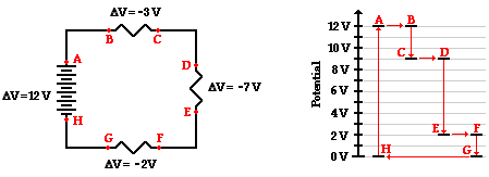
Let's walk through the derivation ourselves. Consider a voltage source connected to three resistors, , , and , in series.
-
Apply KVL: As we did in the last lesson, we sum the voltage changes around the loop. The voltage rise from the source must equal the sum of the voltage drops across the resistors.
This expresses the conservation of energy: the total energy per charge supplied by the source is fully "used" by the resistors.
-
Apply Ohm's Law: We know the current, , is the same through each resistor. We can write the voltage drop across each one using Ohm's Law:
-
Substitute and Solve: Now, substitute the Ohm's Law expressions back into the KVL equation:
Since is a common factor, we can pull it out:
-
Define the Equivalent: Now, imagine replacing the three resistors with a single equivalent resistor, . For this simplified circuit, Ohm's law is:
By comparing this equation to the one we derived in step 3, it's clear that:
This elegant result confirms our intuition: the total resistance of components in series is simply the sum of their individual resistances.
3. Check Your Understanding
Let's solidify this concept. The "Check Your Understanding" section of the Physics Classroom article provides excellent practice.
Physics Tutorial: Series Circuits
Now, test your knowledge with a few quick questions from the same article.
Go to the 'Check Your Understanding' section at the bottom of the page. Answer questions 1 and 2 mentally or on a piece of paper. The answers are provided right below the questions for you to verify your work.
The main takeaways from these questions are:
- As you add more resistors in series, the overall resistance increases.
- Because the total resistance increases (and the voltage is constant), the total current in the circuit must decrease ().
Conclusion
In this lesson, we moved from a qualitative observation to a deep physical and mathematical understanding of series circuits. You now know not just the formula, but the reason it works.
Key Takeaways:
- Physical Cause: Resistors in series increase total resistance because every charge must pass through every point of opposition. The circuit stabilizes to a state where charge accumulation at the resistor boundaries creates the necessary voltage drops to drive a uniform current through the entire loop.
- Mathematical Derivation: The formula for equivalent series resistance, , is a direct consequence of applying KVL (conservation of energy) and Ohm's law to a series loop.
- Effect on Circuit: Adding resistors in series always increases the total equivalent resistance and, as a result, decreases the total current flowing in the circuit.
Preview of the Next Lesson:
We have thoroughly explored what happens when there is only one path for current. The natural next question is: what happens when the current has choices? In the next lesson, we will analyze resistors in parallel. You will discover that, counterintuitively, adding more resistors in parallel decreases the total resistance. We will explore the physical reason for this and derive the corresponding formula for equivalent parallel resistance.