Recommended resources
The freely available resources this lesson will direct you to.
Hello! Welcome back.
In our last lesson, we established the foundation for nodal analysis by learning how to identify nodes, choose a reference, and assign unknown potential variables (v_1, v_2, etc.). We concluded that this set of N-1 node potentials is sufficient to describe the entire state of a circuit.
Today, we build directly on that foundation. Our goal is to translate the physical principle of Kirchhoff's Current Law into a set of solvable mathematical equations. Your learning outcome is to: Formulate KCL equations at each non-reference node in terms of unknown node voltages.
This is the crucial step where the circuit diagram becomes a system of algebraic equations. Mastering this procedure transforms circuit analysis from an ad-hoc process into a systematic, almost algorithmic one—a logical framework that I believe you'll find quite powerful.
1. The Core Principle: KCL in Terms of Node Voltages
From a previous lesson, we know that Kirchhoff's Current Law (KCL) is a statement of the conservation of charge: the total current entering any node must equal the total current leaving it. A common way to state this is:
The algebraic sum of currents leaving a node is zero.
This is the principle we will apply. The key to nodal analysis is how we express these currents. Instead of using variables like i_1 or i_2, we will write each current directly in terms of the node potentials and resistances using Ohm's Law.
For a resistor R connected between two nodes, say node A (at potential v_A) and node B (at potential v_B), the current flowing from A to B is:
This single expression is the engine of nodal analysis.
2. A Systematic Procedure for Writing Nodal Equations
To avoid confusion with signs, we will adopt a consistent convention: For any node we are analyzing, we will assume all unknown currents are flowing out of that node.
This leads to a clear, repeatable process:
- Identify and label: Identify all nodes, choose a reference node (ground = 0V), and label the potentials of all other nodes (
v_1,v_2, ...). This was covered in our last lesson. - Select a node: Pick one of the non-reference nodes to analyze.
- Write the KCL equation: Write one KCL equation for this node by summing the currents leaving it and setting the sum to zero.
- For each resistor connected to the node, the current leaving is
(V_your_node - V_other_side) / R. - For a current source, if it directs current away from your node, it's a positive term in the sum. If it directs current into your node, it's a negative term.
- For each resistor connected to the node, the current leaving is
- Repeat: Repeat steps 2 and 3 for every other non-reference node.
You will end up with N-1 equations for your N-1 unknown node potentials.
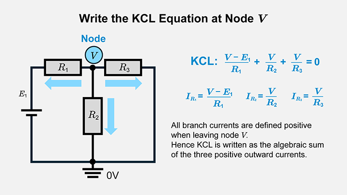
This image provides a perfect illustration of this principle for a single node V.
3. Guided Example: A Circuit with One Unknown Node
Let's apply this method to a circuit that yields a single equation. The goal here is to focus purely on the formulation step.
Nodal Analysis for Circuits Explained
This video provides a clear, narrated example of setting up the KCL equation for a single unknown node. Pay close attention to how the presenter translates the assumed current directions into expressions involving node voltages.
Watch the segment from 01:54 to 04:52. The key steps are: (01:54) Assuming current directions out of the node of interest. (02:50) Writing the initial KCL equation using current variables (e.g., i3 - i1 - i2 = 0). (03:34) The crucial step: replacing each current variable with its Ohm's Law equivalent in terms of node voltages.
Let's walk through that same process with our systematic convention. Consider the circuit from the video.
A circuit with two voltage sources and one unknown node potential, v_a.
- Nodes: We have three nodes. The bottom is the reference (0V). The nodes on the left and right are connected to voltage sources, so their potentials are known: 3V and 2V, respectively. There is only one unknown node potential,
v_a. - Select Node: We select node
afor analysis. - Write KCL: We will sum the currents leaving node
a.- Current leaving through the 2Ω resistor:
(v_a - 3V) / 2Ω - Current leaving through the 4Ω resistor:
(v_a - 2V) / 4Ω - Current leaving through the 1Ω resistor:
(v_a - 0V) / 1Ω
- Current leaving through the 2Ω resistor:
The KCL equation is the sum of these currents set to zero:
This is the formulated equation for the node. Notice that if you assume currents are leaving the node, the node's own voltage (v_a) will always appear as the positive term in each numerator. This is a great way to check your work.
4. Guided Example: A Circuit with Multiple Unknown Nodes
When a circuit has more than one unknown node potential, the process is the same, but you repeat it for each node, generating a system of simultaneous equations.
This article from Khan Academy gives a great step-by-step guide and introduces the excellent mental shortcut of 'doing Ohm's law in your head' as you write the equations.
Read the sections 'Kirchhoff's Current Law at the remaining node' and the 'Guided example'. Focus on how a KCL equation is written for each non-reference node (in the example, nodes b and c), and how each term in the equation corresponds to a current leaving that node.
Let's look at a typical two-node problem.
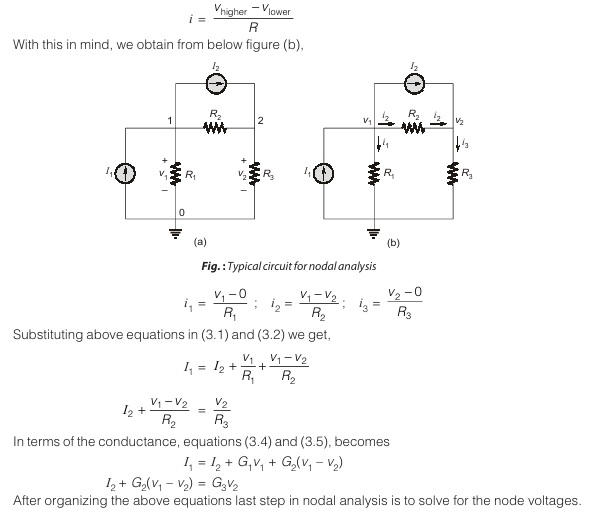
Let's formulate the equations for the circuit in the image above, following our systematic procedure.
Node 1 (at potential v_1):
Sum the currents leaving node 1 and set to zero.
- The source
I_1is entering, so it contributes-I_1to the sum of leaving currents. - Current leaving through
R_1:(v_1 - 0) / R_1 - Current leaving through
R_3:(v_1 - v_2) / R_3
Equation for node 1:
Node 2 (at potential v_2):
Sum the currents leaving node 2 and set to zero.
- The source
I_2is leaving, so it contributes+I_2. - Current leaving through
R_3(flowing fromv_2tov_1):(v_2 - v_1) / R_3 - Current leaving through
R_2:(v_2 - 0) / R_2
Equation for node 2:
We now have two equations and two unknowns (v_1, v_2). The problem has been successfully translated into a system of linear equations.
Your Turn: Practice Formulation
Now it's your turn to apply the procedure. For the circuit below, your task is to write the KCL equations for the non-reference nodes (v_1 and v_2). Do not solve them yet.
A practice circuit with one voltage source, one current source, and two unknown node potentials.
- Identify the non-reference nodes (they are already labeled
v_1andv_2). The bottom node is the ground reference (0V). - Write the KCL equation for node
v_1. - Write the KCL equation for node
v_2.
Click here to see the solution and analysis
Analysis of Node v_1:
We sum the currents leaving node v_1.
- Current leaving to the left through the 10Ω resistor. The node on the other side is at the potential of the positive terminal of the 12V source, which is 12V relative to ground.
- Current leaving downwards through the 2Ω resistor. The node on the other side is ground (0V).
- Current leaving to the right through the 4Ω resistor. The node on the other side is
v_2.
The KCL equation for node v_1 is:
Analysis of Node v_2:
We sum the currents leaving node v_2.
- Current leaving to the left through the 4Ω resistor. The node on the other side is
v_1.
- Current leaving downwards through the 8Ω resistor. The node on the other side is ground (0V).
- The 2A current source is pulling current away from the node, so it counts as a positive leaving current.
The KCL equation for node v_2 is:
You have now successfully formulated a system of two equations for the two unknown node voltages.
Conclusion
Today we've mastered the core procedure of nodal analysis: converting a circuit schematic into a system of equations. This is a major step towards being able to solve any resistive DC circuit, no matter how complex its topology.
Key Takeaways:
- Nodal analysis is the application of KCL at each non-reference node.
- The key is to express each branch current using Ohm's Law in terms of the node potentials:
I = (V_start - V_end) / R. - Adopting a consistent convention, such as "sum of currents leaving the node is zero," makes the process systematic and less prone to errors.
- The result is a system of
N-1linear equations for theN-1unknown node potentials.
Preview of the Next Lesson:
We have successfully set up the problem. The next logical step is to solve it. In the next lesson, we will focus on the algebraic techniques—from simple substitution to more formal methods—to solve the system of linear equations and find the actual numerical values for the node voltages and branch currents. Your strong algebra background will be a great asset here.