Recommended resources
The freely available resources this lesson will direct you to.
Hello! Let's get started on the next stage of your circuit analysis journey.
In our last few lessons, we've built a solid toolkit of shortcuts like series/parallel equivalents and the voltage/current divider rules. These are excellent for analyzing specific circuit patterns. However, to tackle any arbitrary circuit, we need a more powerful and systematic approach. This brings us to Nodal Analysis, one of the most fundamental and versatile methods in circuit theory.
Today, we'll take the crucial first step. Your learning outcome is to: Identify all nodes in a circuit, assign node voltages relative to a reference, and explain why they are sufficient to describe the circuit.
Mastering this foundational skill is like learning to place pieces on a chessboard before learning the moves. It sets up the entire problem-solving framework and is essential for building the deep, systematic intuition you're aiming for.
1. What is a Node?
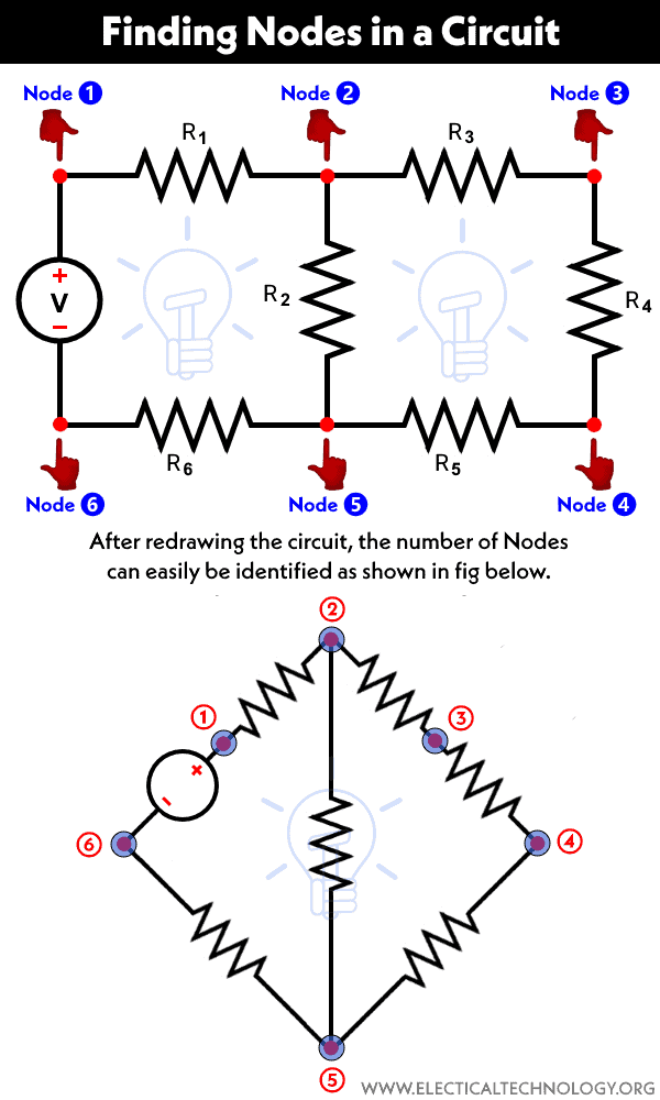
At its simplest, a node is a point in a circuit where two or more components (like resistors, batteries, etc.) are connected. However, a common point of confusion arises from how we draw circuit diagrams. It's crucial to understand that any set of points connected by ideal wires (with zero resistance) is considered a single node, because they are all at the same electrical potential.
Intro to Circuits 15: What is a Node?
To start, let's get a formal definition and immediately tackle the most common misconception. This video from Ben Finio, 'Intro to Circuits 15: What is a Node?', does an excellent job of clarifying this.
Watch the segments from 00:00 to 01:28 and 02:19 to 04:13. Focus on two things: The formal definition of a node and a branch. The key insight that all points connected by a wire are electrically equivalent and thus form a single node, no matter how spread out they look on the diagram.
This idea is so fundamental that it's worth seeing it visualized.

A practical technique for identifying nodes is to "color" all the connected wires. Any continuous stretch of wire that you can color without lifting your pen (and without crossing a component) is a single node.
ECE 100 14 Identifying Nodes in a Circuit Example
Let's see this coloring technique in action. This video by Doug Tougaw demonstrates how to methodically identify and label the nodes in various circuits.
Watch the entire video. Notice how he highlights or encircles each region of connected wire to define a node, even when the circuit's geometry is unusual. This is the exact process you will follow.
2. Node Voltage and The Reference Node
Now that we can identify nodes, we need to associate a quantity with them. In nodal analysis, this quantity is the node potential, which we often call node voltage.
Remember from our first lesson that voltage is fundamentally a potential difference between two points. It doesn't make sense to talk about the absolute voltage at a single point. To solve this, we do what physicists and engineers often do: we establish a reference point. In surveying, heights are measured relative to sea level. In circuits, we choose one node to be our reference node (or ground) and define its potential as 0 Volts.
Then, the "voltage" of any other node is simply the potential difference between that node and our ground reference.
The distinction between the voltage across an element and the potential at a node is subtle but crucial for a clear, logical understanding of nodal analysis.
[PDF] 6.200 Lecture Notes: Circuit Analysis with the Node Method
These lecture notes from MIT provide a precise definition that will appeal to your preference for abstract thinking.
Read the first section (page 1), which starts with 'As mentioned earlier in these notes...'. Pay close attention to the distinction between 'branch voltage' (v) and 'node potential' (e). Also, review the definitions in the 'Glossary and Definitions' section at the end for 'Potential' and 'Reference node'.
So, the process for assigning node voltages is:
- Identify all the distinct nodes in your circuit.
- Choose one node as the reference (ground). By convention, this is often the node at the bottom of the diagram, or the one connected to the negative terminal of a voltage source. A good strategic choice is the node connected to the most elements, as this can simplify calculations later. Assign this node a potential of 0V.
- Assign a variable (e.g., ) to the potential of every other non-reference node.
3. Why Node Voltages are Sufficient
This brings us to the core "why" of this method. Why is this set of node potentials so important?
The answer is that if you know the potential at every node, you can determine every other voltage and current in the entire circuit. The set of node potentials forms a complete, minimal set of variables that fully describes the electrical state of the circuit.
Let's see how this works.
[PDF] 6.01SC Course Notes: Chapter 6, Circuits - MIT OpenCourseWare
The following notes from another MIT course explain exactly why this method is so powerful. It elegantly avoids the complexities and redundancies of trying to apply Kirchhoff's Voltage Law to every possible loop.
Read the section '6.4 Solving circuits' up to the start of '6.4.1 NVCC Method' (pages 246-247). The key takeaway is in the paragraph starting 'One good way to eliminate KVL redundancy is to use node voltages...'. See how the voltage across any element is simply the difference between two node voltages.
As the reading explains:
- To find the voltage across any component: Simply take the difference between the node potentials at its two terminals. For a resistor connected between node A and node B, the voltage across it is .
- To find the current through any component: Once you know the voltage across it, you can use its constitutive equation. For that same resistor, the current is given by Ohm's Law: .
This is incredibly powerful. Instead of needing to define and solve for every single branch current and branch voltage, we only need to solve for the node potentials. Once we have those, everything else can be calculated directly. This simplifies a complex problem down to its essential variables.
Your Turn: Putting it all together
Let's practice on a new circuit.
A circuit for practice.
Follow these steps:
- Identify and count the total number of nodes in this circuit.
- Choose a reference node. Let's use the bottom wire as our ground (0V).
- Label the potentials of the remaining nodes with variables.
Once you've done that, answer this conceptual question:
- Assuming you somehow knew the numerical values for the potentials at the nodes on either side of the resistor, how would you calculate the current flowing through it (from left to right)?
Click here to see the solution and analysis
1. Identify Nodes:
There are 3 distinct nodes in this circuit.
- Node 1: The top left node, connecting the resistor and the resistor.
- Node 2: The top right node, connecting the resistor, the resistor, and the 2A current source.
- Node 3 (Reference): The entire bottom wire, connecting the resistor, the resistor, and the 2A current source.
2. Choose Reference:
We've designated the bottom node (Node 3) as our ground, so its potential is 0V.
3. Label Potentials:
We assign variables to the other two nodes:
- Let's call the potential at Node 1 .
- Let's call the potential at Node 2 .
Conceptual Question Answer:
The resistor is connected between Node 1 (potential ) and Node 2 (potential ).
The voltage drop across the resistor from left to right is .
Using Ohm's Law, the current flowing through it from left to right would be:
This demonstrates how knowing the node potentials is sufficient to find other quantities.
Conclusion
Today, we've laid the essential groundwork for nodal analysis. This is a significant step up from pattern-based rules to a universal, systematic method.
Key Takeaways:
- A node is a region of a circuit where all points are at the same potential, typically connecting two or more components. A continuous wire is a single node.
- We analyze circuits by defining the potential at each node relative to a single reference node (ground), which is set to 0V.
- The set of node potentials is sufficient to describe the entire circuit's state, because any component's voltage or current can be derived from the potentials at its terminals.
Preview of the Next Lesson:
We've learned how to identify our unknown variables (). The next logical question is, "How do we solve for them?" In the next lesson, we will learn how to formulate KCL equations at each non-reference node in terms of these unknown node voltages, turning our circuit diagram into a solvable system of linear equations.