Recommended resources
The freely available resources this lesson will direct you to.
- CAN protocol basics, PART 28, CAN Controller states, Error active, Error Passive and Bus-off.www.youtube.com
- CAN ERROR FRAME AND DIFFERENT TYPES OF ERRORS IN CAN BUSwww.youtube.com
- CAN Bus Errors Explained - A Simple Intro [2025] - CSS Electronicswww.csselectronics.com
- CAN Error Handling - Kvaserkvaser.com
Hello! Welcome to the sixth and final lesson in our module on CAN bus fundamentals.
In our previous lessons, we've focused on how successful communication happens on the CAN bus, from the frame structure and arbitration to the different identifier formats. You now have a solid understanding of how a well-behaved network operates.
However, the true strength of CAN, especially in safety-critical automotive systems, lies in its remarkable robustness. This robustness comes from a sophisticated, built-in system for handling faults. Today, we will explore exactly what happens when things go wrong. This lesson will classify CAN bus error types and describe the powerful error detection and management mechanisms that are part of the protocol.
For your role as both a system tester and a developer, this knowledge is not just theoretical; it's a fundamental diagnostic skill. When you encounter a silent ECU or a flood of strange messages on the bus, understanding the principles we'll cover today is your first step to identifying the root cause.
The Five Layers of Error Detection
The CAN protocol doesn't rely on a single method to catch errors; it employs five distinct mechanisms, creating a highly reliable system. Two of these operate at the bit level, and three operate at the message level.
To get a comprehensive overview of these five mechanisms, please start by reading the following section from an article by Kvaser, a respected manufacturer of CAN tools.
The article 'CAN Error Handling' provides a clear, professional breakdown of the five error detection methods built into the CAN protocol.
Please read the section titled 'Error Detection Mechanisms'. Focus on understanding the names and basic principles of the five checks: Bit Monitoring, Bit Stuffing, Frame Check, Acknowledgement Check, and Cyclic Redundancy Check.
As you've just read, the protocol is constantly cross-checking itself. Let's summarize and categorize these checks based on which node is responsible for the detection:
-
Detected by the Transmitter:
- Bit Error: A transmitter always listens to the bus as it sends a message. If it sends a bit but reads back a different value, it flags a Bit Error. The key exceptions, as we've learned, are during the arbitration field (where losing arbitration is expected) and the ACK slot (where a recessive bit is expected to be overwritten by a dominant one).
- Acknowledgement (ACK) Error: The transmitter sends a recessive bit in the ACK slot. It expects at least one other node on the bus to pull that bit dominant to acknowledge correct reception. If the slot remains recessive, the transmitter knows no node has received the message correctly.
-
Detected by Receivers:
3. Stuff Error: As we know, after five consecutive identical bits, a "stuff bit" of the opposite polarity must be inserted. If any receiver sees a sixth consecutive identical bit, it immediately knows the bit stuffing rule has been violated and flags a Stuff Error.
4. Form Error: Certain parts of a CAN frame have a fixed format (e.g., the CRC delimiter and End-of-Frame must be recessive). If a receiver detects a dominant bit in one of these fixed-format recessive fields, it flags a Form Error.
5. Cyclic Redundancy Check (CRC) Error: The transmitter calculates a 15-bit checksum based on the message content and includes it in the CRC field. Every receiver performs the same calculation on the message it receives. If a receiver's calculated CRC doesn't match the CRC in the frame, it flags a CRC Error.
Sounding the Alarm: The Error Frame
When any node detects one of the errors above, it doesn't stay silent. It immediately broadcasts an Error Frame to inform all other nodes on the network that the last message was corrupt and should be discarded. The Error Frame intentionally violates the bit-stuffing rule to make it unmistakable.
There are two types of Error Frames, which depend on the "health" of the node that sends it.
- Active Error Frame: Consists of 6 consecutive dominant bits. This is transmitted by a "healthy" (Error-Active) node. Because it's a sequence of dominant bits, it overrides any other message on the bus, effectively destroying the corrupt frame and ensuring all nodes see the error.
- Passive Error Frame: Consists of 6 consecutive recessive bits. This is transmitted by a faulty (Error-Passive) node. Because it's recessive, it won't override other bus traffic. The node is essentially "whispering" about the error without having the power to stop the whole conversation.
The video below gives a brief introduction to these concepts.
CAN ERROR FRAME AND DIFFERENT TYPES OF ERRORS IN CAN BUS
To visualize how these error frames work, watch this short segment from the 'CAN ERROR FRAME' video by EMBEDDED LEARNING MADE SIMPLE.
Watch from the beginning to 00:56 to understand the difference between active and passive error frames. Then, you can watch from 01:56 to 05:00 for a review of the error types we just discussed (CRC, ACK, Form, Stuff, and Bit errors).
Fault Confinement: Preventing a "Babbling Idiot"
So, what stops a single, malfunctioning ECU from constantly detecting errors, sending Active Error Frames, and grinding the entire network to a halt? This is where CAN's most elegant feature, fault confinement, comes into play.
Each CAN node maintains two internal counters:
- Transmit Error Counter (TEC)
- Receive Error Counter (REC)
These counters follow a simple set of rules:
- When a transmitter sends an erroneous frame, its TEC increases by 8.
- When a receiver detects an error, its REC increases by 1.
- On a successful transmission or reception, the respective counters are decreased.
This logic correctly assumes that a transmitter is more likely to be the source of an error than a receiver, so it is "punished" more harshly. Based on the values of these counters, a node can be in one of three states:
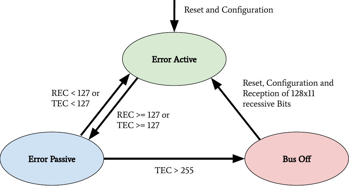
- Error Active: The default state (
TEC < 128andREC < 128). The node participates normally in communication and sends Active Error Frames when it detects a fault. - Error Passive: Entered if
TEC > 127orREC > 127. The node can still participate in communication but can only send Passive Error Frames. It also has to wait an additional period of time after a message before it can try to transmit, giving other nodes priority. - Bus-Off: Entered if
TEC > 255. The node is now considered so faulty that it is completely disconnected from the bus by its own controller. It cannot send or receive any messages until it is reset by the application software.
This state machine gracefully isolates a problematic node from the network. The following state diagram provides a perfect visual summary of these transitions.
To see a clear explanation of this state machine, watch this focused video.
CAN protocol basics, PART 28, CAN Controller states, Error active, Error Passive and Bus-off.
The video 'CAN Controller states' from the Secrets of Automotive Industry channel provides a focused explanation of the three fault confinement states.
Watch the entire video. It clearly explains the TEC and REC thresholds for transitioning between the Error Active, Error Passive, and Bus-Off states.
Test your understanding!
You are testing an ECU on the bench. You notice that after a few seconds of operation, it stops sending CAN messages entirely. Using a debug tool, you read an internal status flag that indicates the CAN controller is in the Bus-Off state.
- What value must the ECU's Transmit Error Counter (TEC) have exceeded?
- Describe a plausible sequence of events that could lead to this state.
- While in the Bus-Off state, can this ECU receive messages from other nodes?
Show answer
- The TEC must have exceeded 255.
- A plausible sequence: The ECU's CAN transceiver has a hardware fault causing it to always read back a different bit level than it transmits (a persistent Bit Error). On its first transmission attempt, it detects the error and its TEC increments by 8. It tries to re-transmit, fails again, and its TEC becomes 16. This continues. After 16 failed attempts (
16 * 8 = 128), its TEC exceeds 127, and it enters the Error-Passive state. It continues to fail transmissions, and its TEC keeps increasing by 8. After another 16 failed attempts (128 + 16*8 = 256), its TEC exceeds 255, and the controller enters the Bus-Off state to isolate itself. - No. In the Bus-Off state, the node is logically disconnected from the bus. It will not transmit, receive, or acknowledge any frames.
From Theory to Practice: Errors in System Testing
As a system tester, you won't just think about these errors abstractly; you'll see them in your logging tools. Knowing how a physical fault translates to a specific CAN error type is a critical debugging skill.
The following are common scenarios you might create or encounter during testing:
-
Scenario: Forgetting the 120-ohm termination resistor on a bench setup.
- Result: The bus voltage levels will be incorrect. A transmitter attempting to send a recessive bit may see a dominant level instead.
- Logged Errors: The transmitter will log Bit Errors. Receivers will likely log Stuff Errors from the resulting invalid bit sequences.
-
Scenario: A logger is connected in "silent mode" to a single broadcasting ECU (so no node is sending acknowledgements).
- Result: The transmitting ECU never sees its messages acknowledged.
- Logged Errors: The transmitter will log a stream of ACK Errors and will repeatedly re-transmit the same message until it goes Error-Passive and then Bus-Off. A listening-only logger would see the error frames generated by the transmitter.
-
Scenario: Two ECUs are accidentally configured to transmit messages with the exact same CAN ID.
- Result: They will arbitrate successfully, but once they start sending their data payload, a bit difference will cause a conflict.
- Logged Errors: Both transmitters will detect a Bit Error at the point of conflict and will send an Active Error Frame.
The CSS Electronics article "CAN Bus Errors Explained" has an excellent section with practical experiments demonstrating these links. You don't need to perform the experiments, but reviewing their findings will be highly valuable for your work.
CAN Bus Errors Explained - A Simple Intro
This resource connects physical faults to the specific CAN error types you would see in a logging tool. This is extremely relevant for system testing and diagnostics.
Please read through the section 'Examples: Generating & logging error frames'. Focus on the descriptions for Test #2 (Removing termination), Test #4 (Removing acknowledging node), and Test #5 (CAN frame collisions). Note the connection between the physical setup and the resulting error types.
Conclusion
This lesson concludes our deep dive into the foundational layers of the CAN protocol. We have explored the sophisticated mechanisms that make CAN a robust and reliable network, a quality that is paramount in the automotive world.
Key Takeaways:
- CAN uses five error detection mechanisms: Bit, Stuff, Form, ACK, and CRC errors.
- Upon detecting an error, a node transmits an Error Frame to invalidate the message for all nodes on the network.
- The fault confinement system uses a Transmit Error Counter (TEC) and a Receive Error Counter (REC) to track the health of each node.
- Based on these counters, a node can be in one of three states: Error Active, Error Passive, or Bus-Off, preventing a single faulty node from disabling the entire network.
- Specific physical faults on the bus (e.g., bad termination, ID collisions) map to predictable CAN error types, which is essential knowledge for diagnostics and testing.
With this solid understanding of how a single CAN frame is reliably transmitted (or gracefully fails), we are now ready to move up the protocol stack. In our next module, we will begin exploring the Transport Layer with ISO-TP (ISO 15765-2), which enables the transmission of diagnostic messages that are much larger than the 8 bytes allowed in a single Classical CAN frame.