Recommended resources
The freely available resources this lesson will direct you to.
Welcome to the first lesson of your course on advanced automotive diagnostics! Your goal is to master UDS and OBD-II for both software development and system testing, and our journey begins here. This initial module builds the foundational knowledge of the entire communication stack, which is essential for understanding how diagnostic requests are sent and responses are received in a modern vehicle.
This first lesson directly addresses a key concept you requested: understanding the fundamental protocol stack. We will map the familiar layers of the OSI model to the specific protocols used in automotive diagnostics: CAN, ISO-TP, UDS, and OBD-II. Grasping this framework is crucial, as it provides a mental model for how these different standards interact to enable everything from reading a simple fault code to reprogramming an entire ECU.
The OSI Model as a Blueprint for Automotive Communication
You may already be familiar with the Open Systems Interconnection (OSI) model from your studies in embedded systems. It's a conceptual framework that standardizes the functions of a telecommunication or computing system into seven abstract layers. While not every protocol fits perfectly, it's an invaluable tool for understanding the separation of concerns in a complex communication stack.
The seven layers are:
- Physical Layer: The hardware level—cables, voltages, signaling.
- Data Link Layer: Manages data transfer between two directly connected nodes, handling framing and error detection.
- Network Layer: Responsible for packet forwarding and routing between different networks.
- Transport Layer: Provides end-to-end communication services, including segmentation, reassembly, and flow control.
- Session Layer: Manages communication sessions between applications.
- Presentation Layer: Translates data between the application and the network format.
- Application Layer: The layer closest to the end-user, containing the protocols applications use to communicate.
Our main goal today is to see how the automotive diagnostic protocols you'll be working with—CAN, ISO-TP, UDS, and OBD-II—fit into this model.
Mapping the Diagnostic Protocols to the OSI Layers
To get a high-level overview of how these protocols relate to the OSI model, please start by watching this short video segment.
Unified Diagnostic Services (UDS) Explained - A Simple Intro [2022]
This video from CSS Electronics provides a concise introduction to how UDS, the CAN bus, and the OSI model are related. It clearly visualizes which protocols operate at which layers.
Watch the section from 06:37 to 08:50. Pay close attention to how it positions CAN, ISO-TP, and UDS within the seven layers.
As the video explained, the diagnostic communication stack is built in layers, with each protocol relying on the services of the one below it. Let's break this down layer by layer.
Layers 1 & 2: The Foundation – CAN Bus (ISO 11898)
At the bottom of our stack is the Controller Area Network (CAN) bus. It is the most common physical network used for diagnostics in vehicles. CAN defines the rules for the two lowest layers of the OSI model.
- Layer 1 (Physical Layer): This is defined by ISO 11898-2. It specifies the physical characteristics of the bus, such as the two-wire differential signaling (CAN_H and CAN_L), voltage levels, and the need for 120-ohm termination resistors at each end of the bus. We will explore this in detail in the next lesson.
- Layer 2 (Data Link Layer): This is defined by ISO 11898-1. It specifies the structure of a CAN message (the "frame"), including the identifier, data payload, and error-checking fields. It also defines the critical bus arbitration process, which we will cover in a future lesson.
In essence, CAN provides the fundamental capability to move small packets of data reliably between ECUs.
Layers 3 & 4: The Bridge – ISO-TP (ISO 15765-2)
A significant limitation of Classical CAN is its very small data payload—just 8 bytes per frame. Diagnostic messages, such as a request to read vehicle identification information or an ECU software update, are often much larger than this. This is where the ISO Transport Protocol (ISO-TP), specified in ISO 15765-2, comes in.
ISO-TP sits on top of the CAN bus protocol and corresponds to the Network and Transport layers:
- Layer 3 (Network Layer): ISO-TP handles addressing, allowing a tester to direct a message to a specific ECU on a shared bus.
- Layer 4 (Transport Layer): This is its primary function. ISO-TP takes a large data packet from the upper layers and performs segmentation, breaking it into multiple pieces that can be sent in consecutive CAN frames. On the receiving end, it performs reassembly to reconstruct the original message. It also manages flow control, allowing the receiver to control the rate at which the sender transmits data.
To understand this crucial relationship between UDS and ISO-TP, the following article provides an excellent explanation.
Relationship between UDS (ISO 14229–1) and ISO-TP (ISO 15765–2)
This article by Berkerturk, 'Relationship between UDS (ISO 14229–1) and ISO-TP (ISO 15765–2)', clearly explains why ISO-TP is a mandatory component when implementing UDS over CAN.
Read the sections 'What is the ISO 15765–2? Why we should use it?' and the paragraph that follows. Focus on understanding why UDS needs a transport protocol like ISO-TP to function over CAN.
Without ISO-TP, sending a UDS request longer than a few bytes would be impossible over a standard CAN bus.
Layers 5 & 7: The User-Facing Services – UDS and OBD-II
Finally, at the top of the stack, we have the application-level protocols that you will interact with most directly as a developer and tester.
-
Layer 5 (Session Layer): Unified Diagnostic Services (UDS), defined in ISO 14229-2, handles session management. For example, the
DiagnosticSessionControl (0x10)service allows a tester to switch an ECU from its normal operating session into aProgramming Sessionor anExtended Diagnostic Sessionto unlock more advanced functions. -
Layer 7 (Application Layer): This is where the core diagnostic services of UDS (ISO 14229-1) and OBD-II (SAE J1979 / ISO 15031-5) reside. These are the protocols that define the "language" of diagnostics.
- UDS: Defines services like
ReadDataByIdentifier (0x22),WriteDataByIdentifier (0x2E), andClearDiagnosticInformation (0x14). - OBD-II: Defines the legislated services (called "Modes") for accessing emission-related data, such as
Mode $01(Show current data) andMode $03(Show stored Diagnostic Trouble Codes).
- UDS: Defines services like
What about Layer 6 (Presentation Layer)? In automotive diagnostics, this layer is generally not defined by a separate protocol. Data formatting rules (like byte order, or "endianness") are typically specified within the UDS/OBD-II application layer standards themselves or are defined by the vehicle manufacturer.
The Complete Picture
The following diagram brings all these pieces together, showing how the entire diagnostic stack maps to the OSI model for communication over CAN.
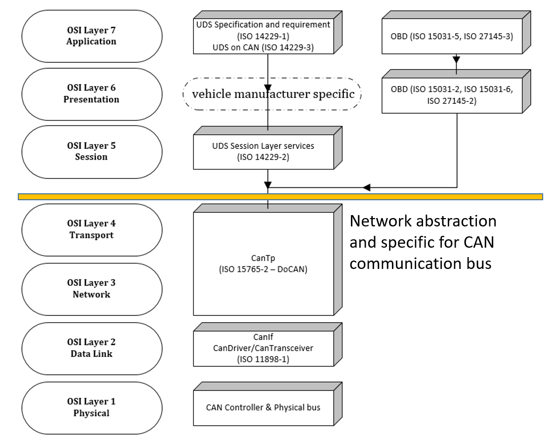
Here is a summary table for quick reference:
| OSI Layer | Automotive Protocol(s) | Key Function |
|---|---|---|
| 7. Application | UDS (ISO 14229-1), OBD-II (ISO 15031-5) | Defines diagnostic services (e.g., Read DTCs, Write Data) and data (PIDs/DIDs). |
| 6. Presentation | (Typically handled by the application layer) | Data formatting, serialization, and encoding. |
| 5. Session | UDS (ISO 14229-2) | Manages diagnostic sessions (e.g., default, programming, extended). |
| 4. Transport | ISO-TP (ISO 15765-2) | Segments large messages into multiple CAN frames and reassembles them. |
| 3. Network | ISO-TP (ISO 15765-2) | Handles addressing for point-to-point diagnostic communication. |
| 2. Data Link | CAN (ISO 11898-1) | Frame structure, bus arbitration, and error checking. |
| 1. Physical | CAN (ISO 11898-2) | Electrical signaling, voltage levels, cabling, and termination. |
Test your understanding!
A software developer is creating a test script to read an ECU's software version, which is a 32-byte string. The request is a UDS ReadDataByIdentifier (0x22) service sent over a Classical CAN bus.
Which protocol is directly responsible for breaking the ECU's 32-byte response into multiple smaller packets before transmission, and at which OSI layers does this protocol primarily operate?
Show answer
The ISO-TP (ISO 15765-2) protocol is responsible for this task. It operates primarily at the Transport Layer (Layer 4) for segmentation/reassembly and the Network Layer (Layer 3) for addressing. The UDS application layer provides the 32-byte payload, but it's ISO-TP that handles the mechanics of splitting it to fit into 8-byte CAN frames.
Conclusion
In this lesson, we established a foundational framework for understanding automotive diagnostic communication. You learned how to map the key protocols—CAN, ISO-TP, UDS, and OBD-II—to the seven layers of the OSI model.
Key Takeaways:
- CAN (ISO 11898) forms the physical and data link layers, providing the basic network infrastructure.
- ISO-TP (ISO 15765-2) acts as the bridge at the network and transport layers, enabling the transmission of large data packets over the payload-limited CAN bus through segmentation.
- UDS (ISO 14229) and OBD-II operate at the session and application layers, defining the actual diagnostic commands and data you will work with.
Understanding this layered architecture is not just theoretical; it is immensely practical for both development and testing. When a diagnostic tool fails to communicate with an ECU, this model allows you to systematically troubleshoot the problem layer by layer. Is it a physical connection issue (Layer 1)? A CAN bus error (Layer 2)? A timing problem in the transport protocol (Layer 4)? Or an incorrect request format (Layer 7)?
In our next lesson, we will begin our deep dive into this stack by focusing on Layer 1: the CAN bus physical layer. We will examine the electrical characteristics, signaling, and bus termination that make communication possible in the first place.