Recommended resources
The freely available resources this lesson will direct you to.
Hello! Welcome to the first lesson of our final module on Applied Power Systems.
In our last lesson, we completed our study of motors by analyzing their efficiency. We made a critical distinction between a motor's efficiency (how well it converts real electrical power into mechanical work) and its power factor (how effectively it draws real power from the grid). This provided a complete picture of a single AC load. Now, we're ready to zoom out from the individual appliance to the large-scale system that powers it: the mains electrical grid.
This lesson addresses the learning outcome: Describe the basic structure of single-phase and three-phase mains power distribution systems. We will explore how electricity is generated and configured to be delivered to everything from the lights in a home to the large machinery in a factory.
Single-Phase Power: The Residential Standard
Most residential and light commercial buildings are supplied with single-phase power. At its heart, single-phase power consists of a single sinusoidal alternating current (AC) waveform.
To understand how this is generated and what it looks like, let's start with a short video.
How 3 Phase Power works: why 3 phases?
The video 'How 3 Phase Power works' from The Engineering Mindset provides an excellent animated explanation of how a simple generator with one coil produces a single-phase AC sine wave.
Please watch the first part of the video, from the beginning to 03:41. Focus on how the rotating magnet and single coil produce one alternating sine wave of voltage and current.
As the video shows, the power delivered by a single-phase system pulsates, hitting zero twice per cycle. While this happens too fast for us to notice in a light bulb, it's a key characteristic of the system.
In practice, how is this delivered to a home? In North America, residential service is typically a 120/240V single-phase, three-wire service. This might sound contradictory, but it's a clever configuration.
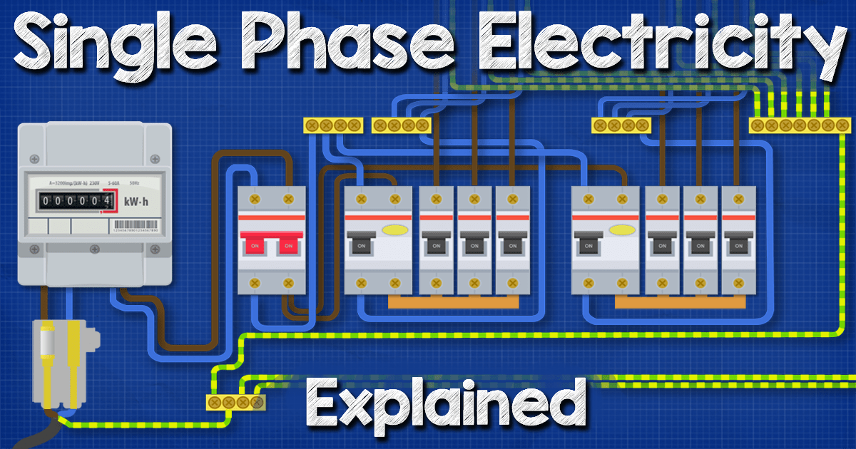
To understand the 120/240V system, let's look at a textual explanation.
Understanding Single-phase and Three-phase Electrical ...
The article 'Understanding Single-phase and Three-phase Electrical Service Configurations' explains this setup clearly.
Read the sections 'What is the difference between single-phase and three-phase electric distribution service?' and 'How does the type of distribution affect voltage options?'. Pay special attention to the description and diagram of the single-phase transformer connection that provides two 'hot' wires and one neutral, allowing for both 120V and 240V circuits.
To summarize the key points from the reading:
- A local transformer provides three wires to the house: two "hot" wires (L1 and L2) and a neutral (N).
- The voltage between L1 and N is 120V, and the voltage between L2 and N is also 120V. Crucially, these two voltages are 180° out of phase with each other.
- Standard outlets and lights are connected between one hot wire and the neutral, receiving 120V.
- High-power appliances like electric stoves, dryers, or EV chargers are connected between the two hot wires (L1 and L2). Since they are 180° out of phase, the potential difference between them is the sum of their magnitudes, giving 240V.
Three-Phase Power: The Industrial Workhorse
While single-phase is sufficient for homes, it has limitations for industrial applications. The pulsating nature of the power delivery is not ideal for running large motors smoothly and efficiently. The solution is three-phase power.
This system uses three distinct AC waveforms, all at the same frequency but offset from each other by 120 degrees ( radians).
How 3 Phase Power works: why 3 phases?
Let's return to the same video, which now beautifully illustrates the move from single-phase to three-phase power.
Watch the segment from 03:41 to 06:08. Observe how adding two more coils at 120-degree intervals creates three phase-shifted sine waves and results in a much more constant and smoother power delivery.
The video highlights the most obvious advantage: near-constant power delivery. This is because as one phase's power is decreasing, another's is increasing, smoothing out the total. There are other significant benefits, which your quantitative background will appreciate.
The technical document 'Three-Phase Power Systems' provides a concise list of the advantages of three-phase power.
Read the introduction section (pages 3-5). Focus on the numbered list of reasons why three-phase is preferred. Pay attention to points about machine size, constant power delivery, and the efficiency of copper usage.
Key Advantages of Three-Phase Power:
- Constant Power: As seen in the video and document, the total power supplied to a balanced load is constant, not pulsating. This results in smoother operation for large motors.
- Higher Power Density: For a given physical size, a three-phase motor or generator can produce about 150% of the power of a single-phase machine.
- Transmission Efficiency: A balanced three-phase system requires only 75% of the copper conductor material to transmit the same amount of power (kVA) as a single-phase system.
Test your understanding!
Considering what you've learned about motors, why is the 'constant power' delivery of a three-phase system particularly beneficial for a large industrial motor compared to the 'pulsating power' of a single-phase system?
Show answer
The torque produced by a motor is directly related to the power delivered. In a single-phase system, the pulsating power results in pulsating torque, causing vibrations and mechanical stress. In a three-phase system, the constant power delivery produces a smooth, constant torque, leading to more efficient operation, longer lifespan, and less vibration in the machinery.
Three-Phase Configurations: Wye vs. Delta
So we have three phases. How do we wire them together? There are two primary configurations: Wye (or Star) and Delta.
How 3 Phase Power works: why 3 phases?
The next segment of the video explains these two fundamental connection types and highlights their most important practical difference.
Watch from 06:08 to 08:55. Focus on how the 'Y' (Wye) connection creates a neutral point, which is essential for supplying single-phase loads. Contrast this with the 'Delta' connection, which does not have a neutral.
Let's formalize this with diagrams and the key voltage/current relationships.
1. Wye (Y) or Star Connection
The ends of the three phase windings are connected to a common central point, the neutral. This creates a 4-wire system (Phase A, Phase B, Phase C, and Neutral).
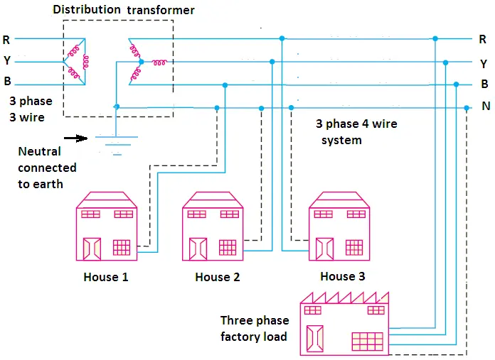
The crucial feature of the Wye connection is that it provides two different voltages:
- Line-to-Neutral Voltage (): The voltage between any one phase and the neutral. This is used for single-phase loads.
- Line-to-Line Voltage (): The voltage between any two phases.
Because the phases are 120° apart, the line-to-line voltage is not simply double the line-to-neutral voltage. The relationship, derived from vector addition, is:
For example, in a system with a 277V line-to-neutral voltage, the line-to-line voltage is . This is commonly written as a 277/480V service.
2. Delta (Δ) Connection
The three windings are connected in a closed loop, resembling the Greek letter Delta (Δ). This forms a 3-wire system (no neutral).
The Delta connection provides only one voltage level: the line-to-line voltage (). It is typically used to serve dedicated three-phase loads, such as large motors, that do not require a neutral connection. In a Delta system, the line current () is related to the current in each phase winding () by:
From Power Station to Consumer
The entire power grid is designed around these principles.
How 3 Phase Power works: why 3 phases?
Finally, let's see a quick overview of the entire journey from the power station.
Watch from 08:55 to 09:54. This segment summarizes how three-phase power is generated, stepped up for long-distance transmission, and then stepped down for local distribution to both commercial (three-phase) and residential (single-phase) customers.
In essence, power is almost universally generated and transmitted as three-phase due to its efficiency. For residential areas, utilities simply tap off one of the three phases from the local distribution line and connect it with the neutral to provide single-phase service. Large commercial or industrial facilities are connected to all three phases to power their heavy equipment.
Conclusion
In this lesson, we have mapped out the fundamental structures of electrical power distribution.
Key Takeaways:
- Single-phase power consists of one AC waveform. It's standard for residential use and can be delivered as a 120/240V three-wire service to power both small and large appliances. Its main drawback is pulsating power delivery.
- Three-phase power uses three AC waveforms, each 120° out of phase. It delivers constant power, is more efficient for transmission, and allows for smaller, more powerful motors. It is the standard for generation, transmission, and industrial use.
- The Wye (Star) configuration has a neutral point, allowing it to supply both three-phase (line-to-line) and single-phase (line-to-neutral) loads from the same system. The key relationship is .
- The Delta configuration is a 3-wire system without a neutral, used primarily for dedicated three-phase loads.
Preview of the Next Lesson:
Now that we understand the structure of the power supply, our next step is to apply this knowledge in a practical context. We'll look at the nameplates on common appliances and learn to interpret their power ratings. The next lesson's objective is to: Calculate the real power consumption of various appliances by interpreting their power factor and apparent power ratings. This will directly connect the concepts of power factor from the last module with the distribution systems we've discussed today.