Recommended resources
The freely available resources this lesson will direct you to.

Hello! Welcome to the second lesson in our module on architecting unified edge security platforms.
In our previous lesson, we designed the architecture for a unified platform at a single edge Point of Presence (PoP). We saw how WAF, Bot Management, and DDoS mitigation can be integrated into a dynamic, multi-stage pipeline.
Now, we face a new challenge. How do we manage the configuration for thousands of these servers spread across hundreds of PoPs globally? When a customer updates a WAF rule, blocks an IP address, or changes a rate-limiting policy, how do we ensure that change is propagated to every server on our network reliably and, critically, within seconds?
This lesson addresses exactly that. Our learning outcome is to: Design a system for distributing security policies to global edge nodes, addressing consistency and latency.
This is a classic large-scale distributed systems problem. We will explore the fundamental architectural patterns for distributing data from a central control system to a massive fleet of clients, analyze their trade-offs, and dissect a real-world system built by Cloudflare to solve this exact problem at internet scale.
1. The Core Problem: Control Plane vs. Data Plane
At the heart of any large-scale managed service is a separation of concerns between two distinct logical components: the Control Plane and the Data Plane.
- Control Plane: The "brain" of the system. This is where configuration is managed, policies are defined, and decisions are made. In our case, this is the central API and UI where a user defines their security rules.
- Data Plane: The "muscle" of the system. This is the fleet of machines that execute the tasks defined by the control plane. For us, this is the global network of edge servers that inspect traffic and enforce security policies.
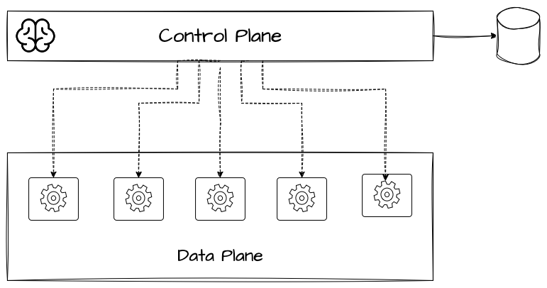
Our entire challenge is to get configuration data from the (relatively small) control plane to the (massive) data plane quickly and reliably.
To solidify this concept, let's watch a brief overview from IBM Technology. It introduces the control plane and data plane as fundamental design principles and discusses how they are applied in a DNS platform, which is a great analogy for our security policy system.
Please watch the following two segments: Introduction (00:00 - 00:47): This introduces the core concepts and their broad applicability. DNS Platform Example (07:01 - 09:43): Pay close attention to how DNS records (our 'policies') are configured in the control plane and then propagated to the data plane resolvers. The discussion on optimizing for consistency in the control plane vs. latency in the data plane is directly relevant to our goals.
As the video highlights, the design of the interaction between these two planes is critical. Let's explore the architectural options.
2. Architectural Patterns for Policy Distribution
The way the data plane gets its configuration from the control plane defines the architecture of the distribution system. There are a few common patterns, each with significant trade-offs.
Avoiding overload in distributed systems by putting the smaller service in control
This article from the AWS Builders' Library provides an excellent analysis of the architectural patterns for control/data plane interaction at massive scale. It directly addresses the problems of overload and latency that we need to solve.
Please read through the main sections of this article to understand the different architectural approaches: Introduction & Overload: Understand the 'simple' architecture where the large data plane calls the small control plane and why this leads to overload and the 'thundering herd' problem. Solving the problem of scale mismatch (S3 pattern): Grasp how using an intermediary like Amazon S3 solves the overload problem but introduces latency, making it unsuitable for rapid policy updates. Reverse the flow of API calls & the long-lived connection pattern: This is the key. Understand how inverting control—having the control plane push updates—solves both overload and latency, and the architectural complexities it introduces.
Let's summarize the patterns from the article in the context of our security platform:
-
Pattern 1: Data Plane Pulls from Control Plane (The Naive Approach)
- How it works: Every edge server periodically polls a central API endpoint (
GET /policies/v1/all). - Why it fails: As the AWS article describes, this creates a massive scale mismatch. A small control plane fleet is easily overwhelmed by synchronized requests from a huge data plane fleet (e.g., after a network partition heals). This is not a viable option for a global system.
- How it works: Every edge server periodically polls a central API endpoint (
-
Pattern 2: Data Plane Pulls from an Intermediate Store (The Decoupled Approach)
- How it works: The control plane periodically writes the entire policy set to a highly scalable object store (like Amazon S3). Edge servers poll the object in S3.
- Pros: Solves the overload problem. The control plane is protected.
- Cons: High Latency. The time to propagate a change is
T_write + T_poll_interval. If the control plane writes every minute and servers poll every minute, a change could take up to two minutes to go live globally. This is too slow for urgent security actions like blocking an active attack.
-
Pattern 3: Control Plane Pushes to Data Plane (The Low-Latency Approach)
- How it works: The control plane actively pushes updates to the data plane. As the article notes, the most robust implementation of this involves data plane servers establishing a long-lived connection (e.g., a persistent gRPC stream) to a control plane node, which can then push updates down this connection.
- Pros: Low Latency. Updates can be pushed out nearly instantaneously. The control plane dictates the pace, preventing overload.
- Cons: Higher implementation complexity. We need a mechanism to distribute the data plane connections across the control plane fleet and a reliable protocol for the push itself.
For our goal of low-latency and reliable policy distribution, Pattern 3 is the clear winner. Let's see how this is done in the real world.
3. Case Study: Cloudflare Quicksilver
Cloudflare faced this exact problem and built a bespoke system called Quicksilver to solve it. Their journey and final architecture provide a masterclass in designing a global configuration distribution system.
Introducing Quicksilver: Configuration Distribution at Internet Scale
This blog post from Cloudflare, 'Introducing Quicksilver', is the primary resource for this section. It details why their old system failed and how they designed Quicksilver from first principles to meet their requirements of speed, reliability, and scale.
This is a detailed read, but it's packed with insights. Please focus on these key parts: 'How KT Worked at Cloudflare' & subsequent problem sections: Read these sections to understand the 'why'. The failures of the previous system (Kyoto Tycoon)—due to write locks, unreliable replication, and corruption—are the requirements for the new system. 'Building Quicksilver' -> 'Storage Engine': Understand why they chose LMDB as the database on each edge server. The key benefits are support for snapshots, low read latency, concurrent access, and its crash-proof design. 'Transaction Logs': This is the most critical section. Understand how they built a replication protocol on top of LMDB using a log with monotonically increasing sequence numbers. This is the core mechanism for ensuring reliability and consistency.
The Quicksilver architecture elegantly solves the challenges of scale, latency, and consistency.
Scaling with a Hierarchical Fan-Out
A single control plane cannot push to tens of thousands of servers. Quicksilver uses a hierarchical replication topology.
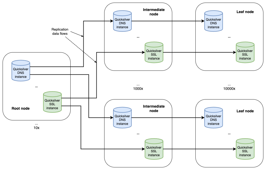
This hierarchical push model allows changes to propagate globally in seconds while ensuring no single node is overwhelmed.
Ensuring Reliability with a Transaction Log
The core of Quicksilver's reliability is its replication protocol, which is essentially a distributed, append-only log.
As described in the article, every change (a SET or DEL operation) is an entry in a transaction log with a unique, monotonically increasing sequence number.
... < 0023 SET “waf-rule-123” “...” < 0024 SET “ip-blacklist” “...” < 0025 DEL “waf-rule-122” ...
When a leaf node connects to an intermediate node, it says, "The last update I saw was #22." The intermediate node then streams all subsequent log entries, from #23 onwards.
This simple mechanism provides powerful guarantees:
- No Lost Updates: If a node misses an update due to being offline, it will automatically receive it upon reconnection because of the sequence gap.
- Correct Ordering: Updates are always applied in the same order everywhere.
- Idempotency & Auditing: The log provides a complete, auditable history of all configuration changes.
The Consistency vs. Availability Trade-off
This log-based replication model provides eventual consistency. There will be a brief period (seconds) where different PoPs might have slightly different policy versions. Is this acceptable? To understand this trade-off, we need to look at what it would take to achieve strong consistency.
Data Consistency and Tradeoffs in Distributed Systems
The desire for perfect consistency leads to deep problems in distributed systems. This video from Gaurav Sen provides an excellent first-principles explanation of these challenges.
Please watch these segments to understand why strong consistency is often impractical at scale: The Two Generals' Problem (08:59 - 13:58): This classic thought experiment shows why it's impossible to achieve agreement over an unreliable network (like the internet). Leader/Follower and CAP (13:58 - 15:50): This connects the problem to the CAP theorem, highlighting the direct trade-off between consistency and availability. Two-Phase Commit (2PC) (15:50 - 24:36): This explains a protocol for achieving strong consistency. Focus on the cost: the system becomes unavailable (it must block reads/writes) while waiting for all nodes to acknowledge a commit. This is unacceptable for a high-throughput edge network.
As the video makes clear, protocols like Two-Phase Commit (2PC) that enforce strong consistency come at the cost of availability and high latency. A global edge platform cannot afford to stop processing traffic while waiting for a policy to be committed in every single location worldwide.
Therefore, a highly reliable eventual consistency model, like the one used by Quicksilver, is the correct engineering trade-off. It prioritizes availability and low latency while using a robust log-based protocol to ensure that the system converges to a consistent state quickly and without losing data.
Conclusion
In this lesson, we designed a system to distribute security policies from a central control plane to a global fleet of edge servers. We've moved from simple-but-flawed polling models to a sophisticated, push-based replication architecture.
Key Takeaways:
- Control Plane vs. Data Plane: Policy distribution is a problem of securely and efficiently propagating state from a central control plane to a distributed data plane.
- Push over Pull: At scale, simple polling (
pull) architectures fail due to the "thundering herd" problem. Push-based architectures, where the data plane maintains a connection and the control plane pushes updates, are superior for low-latency distribution. - Hierarchical Fan-Out: To scale a push model globally, a multi-tiered hierarchy (e.g., root -> intermediate -> leaf) is used to manage replication load.
- The Log is Key: A transaction log with monotonic sequence numbers is the fundamental mechanism for building a reliable replication system that guarantees no lost updates and correct ordering.
- Eventual Consistency is the Right Trade-off: Strong consistency protocols are too slow and reduce availability, making them unsuitable for global edge networks. A well-designed, log-based eventual consistency system provides the necessary speed and resilience.
In our last lesson, we built the security pipeline at the edge. Today, we built the distribution system to get policies to the edge. Now, only one piece remains: how do we get data from the edge?
In our next lesson, we will architect the inverse of Quicksilver: a high-throughput, distributed logging pipeline capable of collecting, aggregating, and processing the trillions of security events generated by our global edge platform every day.