Recommended resources
The freely available resources this lesson will direct you to.
Welcome to your first lesson in the Analog Microelectronic Circuits course. Your background in semiconductor device physics provides an excellent foundation for our work. This course is designed to build on that knowledge, focusing on the practical analysis and design of circuits to help you prepare for your upcoming exam.
This initial lesson addresses a fundamental skill: determining a MOSFET's region of operation. Before we can analyze or design any amplifier, we must first understand the DC state, or bias point, of the transistor. This lesson will equip you with a systematic method to identify whether a MOSFET in a given circuit is in the cutoff, triode (linear), or saturation region.
The Three Regions of Operation
As you'll recall from your device physics studies, a MOSFET's behavior is governed by its terminal voltages. These voltages dictate which of three distinct operating regions the transistor is in. The relationship between drain current () and drain-source voltage () for different gate-source voltages () provides a complete picture.

Let's quickly formalize the conditions for an N-channel enhancement MOSFET with a threshold voltage :
-
Cutoff Region: The transistor is OFF. This occurs when the gate-source voltage is not sufficient to create a channel.
- Condition:
- Behavior: No channel is formed, so the drain current is zero (ideally). The transistor acts like an open switch between its drain and source.
-
Triode (or Linear) Region: The transistor is ON, and the channel is continuous from source to drain. The drain current depends on both and .
- Conditions: AND
- Behavior: The device acts like a voltage-controlled resistor.
-
Saturation Region: The transistor is ON, but the channel is "pinched off" near the drain. The drain current is ideally independent of and is controlled by .
- Conditions: AND
- Behavior: The device acts as a voltage-controlled current source, which is the desired behavior for most amplifiers.
The term is known as the overdrive voltage (). It represents how much the gate-source voltage exceeds the threshold. Using this, the boundary between the triode and saturation regions is simply .
For a quick and clear review of these modes, please watch the following video segment.
The video "38 MOSFET Circuits at DC" from the Microelectronics channel provides a concise summary of the three operating modes and their conditions.
Watch the segments explaining the cutoff region, the triode region, and the saturation region.
The Analysis Strategy: Assume and Verify
In a typical circuit problem, the terminal voltages are not all given; you must solve for them. This creates a "chicken-and-egg" problem: to find the voltages, you need to know the operating region, but to know the region, you need the voltages.
The standard engineering approach to this is a simple, iterative process:
- Assume an operating region. For amplifier circuits, the saturation region is the most common and logical starting assumption.
- Analyze the circuit using the current-voltage () equations corresponding to your assumed region. Solve for the unknown currents and voltages (e.g., , , ).
- Verify your assumption. Check if the voltages you just calculated are consistent with the conditions for the region you assumed. For an NMOS assumed to be in saturation, you would check if and .
- If the conditions are met, your analysis is correct. If not, your initial assumption was wrong. You must then re-analyze the circuit using the equations for the region that the conditions point to (usually the triode region).
This "assume and verify" method is the cornerstone of DC analysis for transistor circuits. The following resource provides a clear outline of this strategy.
Biasing of MOSFET - Solved Example Problems
The webpage "Biasing of MOSFET" from Poriyaan.in provides a concise, step-by-step summary of this analytical method.
Please read the four steps listed under the heading Summary of steps. This text formalizes the strategy we just discussed.
Applying the Strategy: A Worked Example
Let's see this strategy in action. The following video provides a comprehensive walkthrough of a DC analysis problem where the operating region is initially unknown. It clearly demonstrates assuming saturation, solving the circuit equations, and—most importantly—verifying the assumption at the end.
The video "MOSFET Circuits in DC, Part 1" by unwired is an excellent demonstration of the full analysis process.
Please watch the video from the beginning. The instructor first introduces the methodology. Then, he applies it to a circuit, showing how to solve for the voltages and currents under the saturation assumption. Finally, pay close attention to the crucial verification step, where he confirms that the calculated voltages are consistent with saturation mode.
As you saw in the video, solving the circuit often involves a quadratic equation for . You may get two possible mathematical solutions. You can often discard one solution because it leads to a physically impossible scenario (e.g., a voltage drop that exceeds the supply voltage) or it violates a basic condition like .
Practice Problem: A Stacked Configuration
Now, let's apply this knowledge to a problem that requires careful, step-by-step reasoning. This is a common format for university exam questions.
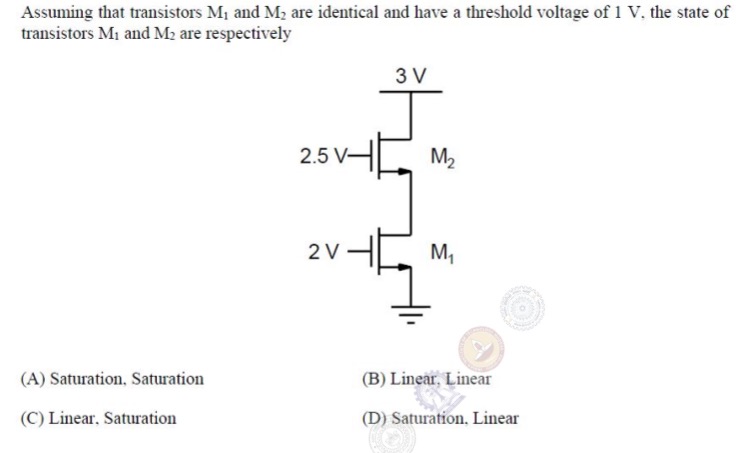
Here, for both transistors. Let's analyze this together.
1. Analyze M2 (the top transistor):
- Gate voltage .
- Drain voltage .
- The source of M2 is connected to the drain of M1. Let's call this intermediate voltage . So, .
- The gate-source voltage is .
- The drain-source voltage is .
For M2 to be ON, we need , which means , or .
Let's check the saturation condition for M2: .
Substituting the expressions: , which simplifies to . This further simplifies to , which is always true.
This is a key insight: If M2 is ON, it must be in the saturation region.
2. Analyze M1 (the bottom transistor):
- Gate voltage .
- Source voltage (ground).
- Drain voltage .
- The gate-source voltage is .
- Since , M1 is definitely ON.
3. Combine the analysis:
- Since M1 is ON, a current must be flowing. Because the transistors are in series, this same current must flow through M2.
- If a current is flowing through M2, it must be ON.
- From our analysis of M2, we know that if it's ON, it must be in saturation.
- Now, what about M1? Its region depends on its drain-source voltage, .
- M1 is in saturation if .
- M1 is in triode (linear) if .
Let's assume M1 is in saturation and see if it leads to a contradiction. If both are in saturation, their currents are:
Since , we can set the expressions equal:
This gives two possibilities for : or .
- The solution would mean , which is less than , turning M2 off. This is a contradiction.
- The solution contradicts our assumption that M1 is in saturation (which required ).
Since the saturation assumption for M1 leads to a contradiction, it must be incorrect. Therefore, M1 must be operating in the triode (linear) region.
Conclusion: M1 is in the linear region, and M2 is in the saturation region. The correct option is (C).
A Note on PMOS Transistors
The analysis for P-channel MOSFETs is identical in principle, but the polarities are reversed. For an enhancement-mode PMOS with a negative threshold voltage , we use absolute values and source-referenced voltages:
- Cutoff:
- Triode: and
- Saturation: and
The "assume saturation and verify" method works exactly the same way. Example 5.7 in the Microelectronic Circuits textbook provides a good worked problem for a PMOS device.
To see how these principles apply to a PMOS transistor, take a look at Example 5.7 in the textbook by Sedra and Smith.
Read through this example. It shows how to determine the bias circuit resistors for a PMOS transistor to operate in saturation and also calculates the maximum drain resistance that maintains this mode.
Key Takeaways
- A MOSFET has three operating regions: cutoff, triode (linear), and saturation. The region is determined by the terminal voltages and relative to the threshold voltage .
- For amplifier applications, the desired region is typically saturation, where the MOSFET acts as a voltage-controlled current source.
- When analyzing a DC circuit, the most effective strategy is to assume the device is in saturation, solve for the circuit's currents and voltages, and then verify that the calculated values are consistent with the saturation condition.
- If the verification fails, you must re-analyze the circuit using the equations for the correct region (usually triode).
In our next lesson, we will build directly on this foundation. Now that you can identify the operating region, we will focus on using the specific equations for the saturation and triode regions to calculate the precise DC operating point of various MOSFET circuits.