Recommended resources
The freely available resources this lesson will direct you to.
Hello! Last lesson, you used a truth table to decide how a multiplexer should be wired. This lesson uses the same design discipline for arithmetic: specify what each bit position must produce, derive logic for that position, and connect positions to make a multi-bit circuit.
You’ll build a full adder from its bit-level behavior, use it in a four-bit adder, and then make the same hardware perform subtraction. The result is a circuit whose outputs have precise meanings—an essential habit when you later describe arithmetic hardware in RTL.
Start with one bit position
A single bit position cannot hold the value 2. When two input bits are both 1, their sum is binary : the sum bit is 0, and a carry bit of 1 belongs in the next position.
A half adder implements the case with two inputs and no incoming carry:
| Sum | Carry | ||
|---|---|---|---|
| 0 | 0 | 0 | 0 |
| 0 | 1 | 1 | 0 |
| 1 | 0 | 1 | 0 |
| 1 | 1 | 0 | 1 |
The sum is 1 when exactly one input is 1; the carry is 1 when both are 1. Thus the two output functions are and . One XOR gate and one AND gate realize this specification.
Watch the opening of Combinational Devices 1: Half Adder and Full Adder from Down to the Wires. It develops the half adder from binary addition, then shows why its missing carry input matters when adding multi-bit values.
Combinational Devices 1: Half Adder and Full Adder
Watch Combinational Devices 1: Half Adder and Full Adder from Down to the Wires to see how a bit-level arithmetic rule becomes a circuit.
Watch the half adder for the sum and carry outputs. Continue with the limitation: focus on the bit position that must account for a carry produced by the position to its right.
A half adder is useful at a position known to have no carry-in. For a reusable stage in a multi-bit adder, however, carry-in must be an input, not an assumption.
Design a full-adder stage
A full adder has three one-bit inputs: operand bits and , and an incoming carry . Its two outputs must satisfy this numerical specification:
The right-hand side expresses the result as a bit at the current position plus a carry worth two at the next position. Since three input bits can total 0, 1, 2, or 3, one sum bit and one carry bit cover every case.
| 0 | 0 | 0 | 0 | 0 |
| 0 | 0 | 1 | 1 | 0 |
| 0 | 1 | 0 | 1 | 0 |
| 0 | 1 | 1 | 0 | 1 |
| 1 | 0 | 0 | 1 | 0 |
| 1 | 0 | 1 | 0 | 1 |
| 1 | 1 | 0 | 0 | 1 |
| 1 | 1 | 1 | 1 | 1 |
Two patterns turn this table into gates. The sum is 1 when an odd number of inputs are 1. The carry is 1 when at least two inputs are 1. Define ; then:
The carry equation separates two reasons for a carry. If , the stage generates a carry regardless of its carry-in. If exactly one of is 1, an incoming carry passes through. These equations specify one straightforward gate implementation: form with XOR, use it for the sum and one carry term, then OR the two carry terms.
Continue the same video to see the three-input truth table and the derivation of both output functions. You have already used Karnaugh maps, so concentrate on how the resulting logic matches the arithmetic specification rather than on map mechanics alone.
Combinational Devices 1: Half Adder and Full Adder
Continue Combinational Devices 1: Half Adder and Full Adder for the full-adder truth table and output logic.
Watch carry derivation, particularly the cases in which at least two inputs are 1. Then watch sum derivation and connect its XOR result to odd parity in the truth table.
The numerical specification is also a compact way to check a proposed design. For example, inputs , , total 2. The outputs must therefore be , —not merely whichever values a plausible-looking gate arrangement happens to produce.
Connect stages into a four-bit adder
Let and be four-bit operands, with index 0 denoting the least significant bit. Give stage inputs , , and . It produces result bit and carry . For ordinary addition without an incoming carry, set .
The key connection is that each stage’s carry-out supplies the next stage’s carry-in. This is a ripple-carry adder: even though all operand bits are presented together, an upper stage may need the carry calculated by a lower stage.
The video gives a brief view of the connected stages:
Combinational Devices 1: Half Adder and Full Adder
Finish the relevant portion of Combinational Devices 1: Half Adder and Full Adder to see how full-adder stages form a multi-bit circuit.
Watch the cascade. Identify the initial carry at the least significant stage and the final carry beyond the most significant stage.
For a concrete trace, add and . At bit 0, produces . At bit 1, produces . At bit 2, produces . Finally, bit 3 adds , producing . Reading the result in its usual order gives , or 10.
Specify the output width. Four-bit operands can produce a five-bit unsigned sum: , for example, yields and . If the interface exposes only , its four bits wrap to zero. If the interface exposes as well, the full result is . Neither behavior is inherently wrong; the circuit specification must say which result is required.
Reuse the adder for subtraction
A fixed-width subtractor need not implement borrowing as a separate chain of gates. Recall that, within four bits, the two’s complement of is formed by inverting its bits and adding 1. Thus the low four result bits of can be calculated by adding , the bitwise complement of , and an initial carry of 1.
Watch the subtraction explanation in 4-bit Adder and Subtractor Circuit Explained from ALL ABOUT ELECTRONICS. It shows why the inversion and the added 1 are both necessary.
4-bit Adder and Subtractor Circuit Explained
Watch 4-bit Adder and Subtractor Circuit Explained from ALL ABOUT ELECTRONICS to connect fixed-width two's-complement subtraction to adder hardware.
Watch subtraction as addition. Follow the four-bit example and distinguish the four retained result bits from the final carry-out.
To make one circuit perform either operation, introduce a mode input . Feed each through an XOR gate with , and connect to the first stage’s carry-in:
Each full-adder stage now receives . The two modes follow directly from XOR behavior:
| Mode | Input supplied in place of | Initial carry | Operation in the result bits |
|---|---|---|---|
| 0 | 0 | ||
| 1 | 1 |
The mode must control both the XOR gates and . Inverting without setting would leave the subtraction one too small.
Watch the video’s unified-circuit explanation, then inspect the supplied diagram.
4-bit Adder and Subtractor Circuit Explained
Continue 4-bit Adder and Subtractor Circuit Explained to see how one control signal selects addition or subtraction.
Watch mode control. Track where the control signal goes: it conditionally inverts every B bit and supplies the initial carry.
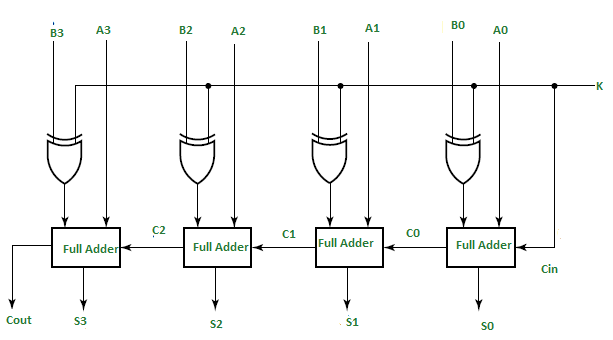
In the diagram, follow the circuit from right to left: bit 0 is the rightmost full adder, and its carry feeds bit 1. The label at the left is the carry leaving bit 3. Setting passes all bits unchanged and starts with carry 0. Setting inverts all bits and starts with carry 1.
Interpret and check the outputs
The four result bits are the low four bits of the selected arithmetic operation. They do not, by themselves, say whether you intended an unsigned or signed two’s-complement interpretation.
Consider subtraction with and . In subtraction mode, the adder receives , the inverted value , and initial carry 1. The result is : the low bits represent 2.
Reverse the operands: , . Now the result is . As a four-bit two’s-complement value, represents . As an unsigned value, those same bits represent 14—the wrapped four-bit result. The operation and the chosen number interpretation determine what you report.
For unsigned subtraction in this design, the final carry has a useful status meaning: means no borrow (); means a borrow was needed (). During unsigned addition, instead indicates a carry beyond four bits. Do not label it simply “overflow” without defining the intended arithmetic. Signed overflow is a different condition: for example, four-bit signed produces , even though is outside the signed four-bit range of through . Here , so carry-out alone would miss the signed overflow.
A sound bit-level design therefore states its contract before choosing gates: operand width, whether an incoming carry is allowed, which mode performs which operation, which result bits are retained, and whether carry, borrow, or signed-overflow status is required. The full-adder truth table establishes each stage’s behavior; checking representative cases such as a carry across several positions, a result beyond four bits, and subtraction in both operand orders establishes that the connections and output interpretation match that contract.
Key takeaways
A full adder turns three input bits into a sum bit and a carry bit according to . Connecting its carry outputs to successive carry inputs produces a multi-bit ripple-carry adder. Conditional XOR gates on , with the same mode signal used as the initial carry, let that adder compute either or . Always define the result width and status-bit meaning alongside the logic.
Next, you’ll examine how long a combinational path takes to settle and why changing inputs can briefly produce glitches—particularly relevant when a carry must travel through several stages.