Hello! Welcome back to our design of the rotary indexing mechanism.
In the previous lesson, we populated our digital workspace with the core transmission components: the 24-tooth and 72-tooth S8M pulleys and the timing belt connecting them. This was a crucial step in simulating a real-world workflow, using both sourced COTS parts and automated modeling tools.
Now that we have our pulleys, we need to design the components that will locate them and transmit their motion. This brings us to today's learning outcome: Design and model the main shafts based on the transmission layout. We will design both the input shaft (driven by a motor) and the output shaft (which will eventually drive our indexing plate).
This lesson will guide you through the systematic process that a design engineer follows, moving from load analysis and hand calculations to creating a detailed 3D model in Onshape. Your background in mechanical engineering will be a great asset here, as we'll be applying fundamental principles of mechanics and materials.
1. The Shaft Design Process: From Sketch to Solid
A robust shaft design doesn't start in CAD. It starts with a clear understanding of the forces at play and a preliminary layout. We will follow a three-phase process common in industry:
- Layout and Load Analysis: Define the shaft's function and determine the forces acting on it.
- Sizing and Material Selection: Perform calculations to determine the required diameter to handle the loads safely.
- Detailed Modeling: Create the 3D model in Onshape, incorporating features for mounting components like pulleys, bearings, and keys.
To ground our design process, we'll follow a structured guide.
Design Shaft Design: A Step-by-Step Guide
The article 'Shaft Design: A Step-by-Step Guide' from Mechnexus provides an excellent overview of the entire shaft design workflow. We will use it as our roadmap for this lesson.
First, please read 'Phase 1: Define the Problem & Initial Layout'. This section covers the critical first steps of identifying loads, sketching a layout, and selecting a material.
2. Phase 1: Layout and Load Analysis for Our Project
Let's apply the principles from the Mechnexus article to our rotary indexer. We need to design two shafts: an input shaft for the 24T pulley and an output shaft for the 72T pulley.
A. Preliminary Layout Sketch
First, sketch a simple free-body diagram for each shaft. Each shaft will be supported by two bearings and will have a pulley mounted on it. For the input shaft, we'll assume the torque comes from a motor coupler on one end.
Your sketch for the input shaft should look something like this:
- A horizontal line representing the shaft.
- Two triangles representing simple supports (bearings).
- A downward force
F_beltat the location of the 24T pulley, representing the tension from the belt. - An input torque
T_inacting on the shaft.
B. Determine Loads
Now, let's quantify these loads.
-
Torque (T): Let's assume our system is driven by a motor providing 100 Watts of power. The input shaft, holding the 24T pulley, spins at 500 rpm.
The torque on the input shaft is:
The output shaft has a 3:1 gear reduction, so its speed is rpm, and its torque is: -
Bending Force (F): The belt tension creates a bending force on the shaft. This is a combination of the tension needed to transmit torque and the belt's required pre-tension. A common engineering approximation is that the total bending force is a multiple of the tangential force required for torque transmission.
The tangential force on the input pulley (pitch diameter mm) is:
For timing belts, the total bending forceF_beltcan be estimated as 1.5 to 2 times the tangential force. Let's use a conservative factor of 2.
This force acts on both pulleys.
C. Material Selection
As suggested in the Mechnexus article, a medium-carbon steel is a great general-purpose choice. Let's select AISI 1045 Cold Drawn Steel, which is strong, readily available, and reasonably priced. From standard material tables, we find:
- Ultimate Tensile Strength (): 625 MPa
- Yield Strength (): 530 MPa
3. Phase 2: Shaft Sizing Calculation
With our loads and material defined, we can now calculate the required shaft diameter. We'll focus on the most critical point: the section of the shaft where the pulley is mounted, as it experiences both bending and torsion.
This video and article explain the theory and formulas used for shaft sizing under combined loads.
This document from the University of Florida, 'Shaft Design,' provides the detailed engineering formulas we need. It covers force calculations for transmission elements and the combined stress equations for sizing.
Please skim through these sections to understand the concepts. Focus on: Stress Concentrations (slides 15-21): Look at the 'Preliminary Design Values for Kt' for keyseats and fillets. We'll need these. Design Stresses for Shafts (slides 21-28): Understand the difference between steady torsional stress and reversed bending stress. The final design equation (slides 29-32): Pay close attention to the final derived equation for diameter 'D' on slide 32. This is the formula we will use.
The final design equation presented in the resources, often referred to as the ASME shaft equation, combines the effects of bending and torsion:
(Note: Some formulations use for torsion and some use . We will use the more modern approach based on the distortion energy theory as shown in the UFL slides which leads to the formula below, slightly different but based on the same principles.)
A more direct form from the UFL slides is:
Let's break this down and calculate the required diameter for our input shaft at the pulley location.
- Bending Moment (M): Assuming the pulley is centered between two bearings 80mm apart, the maximum bending moment is . As the shaft rotates, this is a fully reversed, alternating moment ().
- Torque (T): This is our steady, midrange torque .
- Design Factor (N): For a typical industrial application with well-understood loads, a factor of safety of 2.0 is reasonable.
- Stress Concentration Factor (): The pulley will be fixed with a key. From the UFL slides, a good preliminary value for a profile keyseat is .
- Endurance Limit (): For steel, the theoretical endurance limit is . This value is then reduced by various factors (size, surface finish, etc.), but for a preliminary design, we can use a derated value. Let's estimate .
- Yield Strength (): 530 MPa.
Plugging these into the equation:
This gives a diameter of 7.5 mm.
This seems small. Let's quickly check with the simpler torsion-only formula from the Mechnexus article for comparison:
Using a conservative allowable shear stress :
The calculations suggest a very small diameter is needed for strength alone. However, in practice, factors like bearing availability, stiffness (deflection), and manufacturability dictate a larger size. The bore of a standard 24T S8M pulley is often 8mm or larger. Let's choose a nominal diameter of 12 mm for the input shaft and 16 mm for the higher-torque output shaft. This provides a large margin of safety and is a more practical starting point.
Test your understanding!
In our calculation, we used a stress concentration factor . Where would this stress concentration physically exist on the shaft, and what design feature causes it?
Show answer
The stress concentration would exist at the edges of the keyway, which is the slot milled into the shaft to hold the key that transmits torque to the pulley. The sharp corners of the keyway interrupt the flow of stress, causing it to concentrate in that area.
4. Phase 3: Modeling the Shaft in Onshape
Now, let's model our 12 mm input shaft in Onshape. The most efficient way to model a cylindrical, stepped part like a shaft is with the Revolve feature.
- Create a Sketch: In a new Part Studio, create a sketch on the Front plane.
- Draw the Centerline: Draw a horizontal construction line passing through the origin. This will be your axis of revolution.
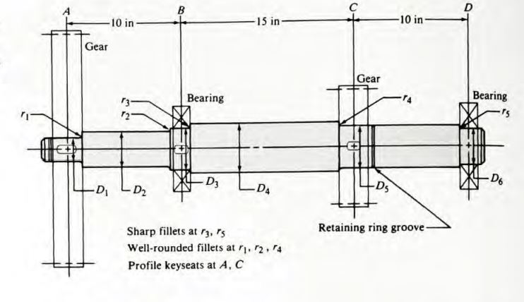
- Sketch the Profile: Draw the 2D profile of one half of the shaft above the centerline. A typical shaft has steps for bearings, the main component (our pulley), and retaining features. A good starting profile would have:
- A section for the motor coupling.
- A step up for the inner bearing seat.
- The main section for the pulley.
- A step down for the outer bearing seat.
- Make the main section diameter mm from the centerline. Step the bearing seats down to 5 mm radius (for a 10mm ID bearing).
- Revolve: Select the Revolve tool, choose your sketched profile as the face, and select the construction line as the revolve axis.
- Add Features:
- Keyway: Use the Extrude-Remove tool with a rectangular sketch on the surface of the shaft to create a keyway for the pulley.
- Fillets: Add fillets at all the "steps" where the diameter changes. As discussed in the UFL slides, generous fillets significantly reduce stress concentration.
- Chamfers: Add small chamfers to the ends of the shaft to make assembly easier.

Your Task for Today's Session
Your assignment is to design and model both shafts for our project.
- Create a new Part Studio in your Onshape document named "Shafts".
- Model the Input Shaft:
- Based on our discussion, create a shaft with a nominal diameter of 12 mm where the 24T pulley will sit.
- Design steps for two bearings (e.g., 10 mm diameter for a standard 6800 bearing).
- Add a keyway for the pulley.
- Model the Output Shaft:
- Follow the same process for the output shaft, but use a nominal diameter of 16 mm to handle the higher torque.
- Design steps for appropriate bearings (e.g., 15 mm diameter for a standard 6802 bearing).
- Add a keyway for the 72T pulley.
Focus on creating the stepped geometry using the Revolve feature and adding the keyway. We will address more advanced features like retaining ring grooves in a later lesson.
Conclusion
Today, you've completed a full cycle of the mechanical design process for a critical component. You started with requirements, performed load and stress analysis to inform your design, and then translated those specifications into a 3D CAD model.
Key Takeaways:
- Shaft design is an iterative process that balances strength calculations with practical considerations like standard component sizes and manufacturability.
- A systematic approach (Layout -> Loads -> Size -> Model) ensures all requirements are met.
- Stress concentrations at features like keyways and shoulder fillets are critical and must be accounted for in the design stage.
- The
Revolvefeature in CAD is the primary tool for efficiently modeling cylindrical parts like shafts.
Preview of the Next Lesson:
With our shafts and pulleys modeled, we now need to hold them in place. In the next lesson, we will design the mounting strategy and model necessary support features (e.g., brackets, plates). This will involve selecting specific bearings for our shaft diameters and designing the stationary structure that will form the backbone of our rotary mechanism.