Hello! Welcome back to the design phase of our rotary indexing mechanism.
In the last lesson, we did the foundational engineering work of selecting and sizing the primary transmission components. We determined that a timing belt system using an S8M belt, 30mm wide, with a 24-tooth and a 72-tooth pulley would meet our 3:1 reduction requirement. We also explored the calculations for a gear-based alternative.
Today, we transition from calculations on paper to components in our digital workspace. This lesson directly addresses the learning outcome: Source or model the transmission components in OnShape. We will cover the two primary workflows that engineers use to populate their CAD assemblies: sourcing standard parts from external libraries and modeling custom components using specialized tools within OnShape.
By the end of this lesson, you will have the 3D models of the pulleys and belt for our rotary indexer, ready for the next stage of our design.
1. Sourcing vs. Modeling: The Engineer's Workflow
As a design engineer, one of your constant considerations is "make vs. buy." In the world of CAD, this translates to "model vs. source." For common, off-the-shelf components like fasteners, bearings, pulleys, and motors, it is standard practice to source existing 3D models rather than spend time modeling them from scratch. For custom components, like a specialized bracket or a gear with non-standard parameters, you will model them yourself.
Today, we'll practice both. We will source our standard timing pulleys and model our gears and belt using powerful automation tools in OnShape.
2. Sourcing Standard Components
Sourcing is the process of finding a pre-made CAD model of a commercial off-the-shelf (COTS) part and importing it into your project. There are two main ways to do this:
A. Supplier Websites (e.g., McMaster-Carr, MISUMI)
Most major industrial suppliers provide 3D models of their products, typically in neutral formats like STEP or Parasolid (.x_t). The workflow is:
- Navigate to the supplier's website and find the exact part number you need.
- Download the associated 3D CAD model.
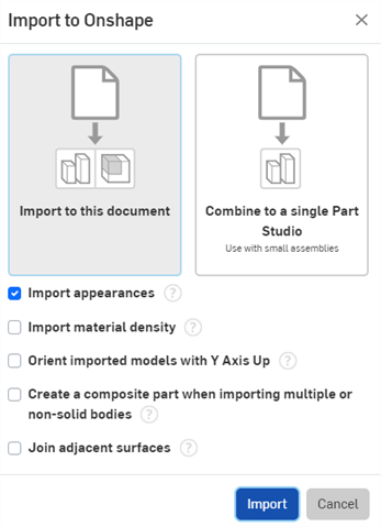
- Import the file into your Onshape document.
B. Integrated Part Libraries (e.g., MKCad)
A more streamlined approach involves using part libraries integrated with OnShape. MKCad is a popular, community-maintained library for robotics and machine design components. It contains a vast collection of COTS parts that can be inserted directly into your assembly without leaving OnShape.
Let's learn how to access and use this powerful resource.
Onshape Part Libraries, Feature Scripts, and addons
This guide from Pearce Robotics explains what MKCad is and how to effectively add its libraries to your Onshape account for easy access. This is a critical skill for rapid prototyping.
Please read the first section, 'MKCad (Part Libraries)'. Focus on the instructions for finding the official MKCad libraries (owned by 'Ricky Marcus' or 'Milkenknights Test Account') and adding a label to them for quick access. This will set you up for the next step.
Once you have labeled the MKCad libraries, you can go to the "Insert" dialog in an Assembly tab, click on "Other documents," and use your "-MKCad" label to filter and search for parts. For our project, you would search for something like "S8M pulley 24 tooth" and "S8M pulley 72 tooth" to find the components we specified in the last lesson.
3. Modeling with FeatureScripts
For components that aren't standard or have geometry defined by mathematical relationships (like gears and belts), Onshape's FeatureScripts are incredibly powerful. A FeatureScript is a small program that automates the creation of complex features. You input the key parameters, and the script generates the geometry for you.
A. Modeling Spur Gears
Let's imagine our design required a custom gearset. In the last lesson, we calculated a potential 30:1 ratio, which would need a compound gear train. Let's model a single 5:1 stage.
The following video provides an excellent, concise walkthrough of using the built-in Spur Gear FeatureScript.
This video, 'Onshape How To: Gears,' will guide you through the entire process of activating and using the Spur Gear FeatureScript to create a perfectly meshing pair of gears.
Please watch from 00:42 to 09:43. The video covers three key steps that we will follow: Adding the custom feature to your toolbar (00:42 - 02:22). Creating the first gear by defining its parameters (02:22 - 05:26). Creating the second gear, ensuring it meshes correctly by using the same 'module', and positioning it at the correct center distance (05:26 - 09:43).
Let's recap the key steps from the video for creating a 5:1 gear ratio (e.g., a 20-tooth pinion and a 100-tooth gear):
- Add the FeatureScript: Click the
+(Add custom features) icon ->FeatureScript samples-> Filter for "gear" -> SelectFeatureScript Spur Gear. - Create the Pinion (Small Gear):
- Start the
Spur Gearfeature. - Set Number of teeth to 20.
- Set a Pitch circle diameter (e.g., 2 inches).
- Note the Module that Onshape calculates. This value is critical. It defines the size of the teeth.
- Set the Depth (thickness) and add a Center bore.
- Start the
- Create the Gear (Large Gear):
- Start a new
Spur Gearfeature. - Set Number of teeth to 100.
- Crucially, instead of setting the diameter, copy the exact Module value from the first gear. This guarantees the teeth will mesh. Onshape will calculate the correct pitch circle diameter for you.
- To position the second gear correctly, you'd create a sketch line representing the center distance before creating the gear, then use the
Move originoption in the gear feature, as shown in the video. The center distance is the sum of the two pitch radii: .
- Start a new
Test your understanding!
You are using the Spur Gear FeatureScript to create two gears. You've created the first gear. What is the single most important parameter you must ensure is identical when creating the second gear to guarantee the teeth will mesh correctly?
Show answer
The module (or diametral pitch, if using imperial units) must be identical for both gears. This parameter defines the size and profile of the gear teeth, and only gears with the same module can mesh together.
B. Modeling a Timing Belt
Just like with gears, there is a specialized FeatureScript for creating belts. This tool is a perfect example of design automation, saving you from the tedious process of sketching a complex belt path manually.
How Custom Features Make Belt Routing Easy
This Onshape Tech Tip, 'How Custom Features Make Belt Routing Easy,' explains the benefit of the Belt feature and shows you exactly how to add it to your toolbar.
Read the article, focusing on the section 'Adding the Belt Feature to your Toolbar'. This will give you the steps to add the belt generator to your Onshape environment.
The workflow for using the Belt feature is typically:
- Place your pulleys (which you sourced from MKCad) in an Assembly at the correct center distance.
- Start the Belt feature.
- Select the circular faces or mate connectors of the pulleys.
- The tool generates the belt part, often automatically calculating the nearest standard belt length.

Your Task for Project 2
Now it's time to apply these workflows to our rotary indexing mechanism.
- In your Onshape project document, create a new Part Studio. Name it "Transmission Components".
- Using the methods described, either from MKCad or a supplier's website, source and insert the two pulleys we specified:
- One S8M pulley with 24 teeth.
- One S8M pulley with 72 teeth.
- Ensure they both are specified for a 30mm wide belt.
- Add the Belt FeatureScript to your toolbar. You may need to create a temporary assembly with your two pulleys to generate the belt part, which you can then use in your main assembly later. Try generating the S8M belt that connects them.
Conclusion
In this lesson, you've learned the essential, practical skills of populating a CAD model with both standard and custom transmission components. This is a direct simulation of a real-world engineering workflow.
Key Takeaways:
- Source, don't model: For standard COTS parts like pulleys, always look for a model from a supplier or a library like MKCad first.
- Embrace automation: Use Onshape's FeatureScripts to rapidly generate complex, parametric geometry like gears and belts. This saves time and reduces errors.
- Connect theory to practice: The parameters in the FeatureScripts (like
moduleorpitch) directly correspond to the engineering principles we used for sizing in the previous lesson.
Preview of the Next Lesson:
With our primary transmission components now modeled, our next step is to design the parts that will hold them. In the next lesson, "Design and model the main shafts based on the transmission layout," we will begin designing the shafts for our pulleys, considering factors like diameter, length, and features for mounting.