Hello! In our last lesson, we dove deep into the world of manufacturing variation by conducting a tolerance stack-up analysis. You learned how to guarantee that your parts will fit together by analyzing the cumulative effect of their tolerances.
Today, we'll expand our focus from "Will it fit?" to two equally critical questions for a professional engineer: "Can we build this efficiently?" and "What could go wrong?" This lesson directly addresses the learning outcome: Perform a risk assessment (FMEA) and apply DFMA principles to the design.
These two methodologies, Design for Manufacture and Assembly (DFMA) and Failure Mode and Effects Analysis (FMEA), are cornerstones of a robust design process. They are exactly the kind of documented, systematic thinking that turns a good design into a great, commercially viable product. Mastering them is a significant step in building the professional engineering workflow you aim to showcase in your portfolio.
1. Designing for Reality: An Introduction to DFMA
Design for Manufacture and Assembly (DFMA) is a design philosophy focused on creating products that are easy and economical to produce. It's composed of two interrelated concepts:
- Design for Manufacture (DFM): Optimizing the design of individual parts to make them easier to manufacture.
- Design for Assembly (DFA): Optimizing the product structure to make it easier to assemble.
The core idea is to consider the manufacturing and assembly process at the earliest stages of design, where changes are cheap and easy to make. This prevents discovering later that your "perfect" design is unnecessarily expensive or impossible to build at scale.
To get a feel for the formal structure of this process, let's look at a professional guideline.
Design for Manufacture & Assembly Guideline
This 'Design for Manufacture & Assembly Guideline' from the Construction Innovation Hub, while from a different industry, provides an excellent, universal overview of the DfMA methodology. We'll use it to understand the core principles.
Please read the following sections: Introduction (pages 7-10): Focus on the 'Basic Overview' and 'Benefits' sections. Note the key principles like optimizing part count and standardizing parts. Functional Analysis (pages 14 and 17-18): This is a powerful technique. Pay close attention to the three key questions used to determine if a part is truly essential. Don't worry about the quantitative formulas for now; focus on the concepts.
A Key DFA Principle: Part Count Reduction
As you saw in the guideline, one of the most effective DFA principles is minimizing the number of parts. Every part adds cost—not just for the part itself, but for its documentation, procurement, handling, and assembly.
The Functional Analysis you just read about gives you a simple, powerful test. For each part in your assembly, ask:
- Does the part move relative to other parts during operation?
- Must the part be of a different material or be isolated from others?
- Must the part be separate to allow for service, replacement, or disassembly?
If the answer to all three questions is "No," that part is a prime candidate for elimination or integration into another part.
DFM in Practice: Process Dictates Design
While DFA focuses on the assembly structure, DFM is about the design of individual components. A critical aspect of DFM is that your design choices must align with the capabilities and constraints of your chosen manufacturing process. A feature that is easy to 3D print might be impossible to CNC machine.
The following video gives an excellent overview of the design rules for several common manufacturing processes. Since you're working on projects that will likely involve machined or 3D printed parts, these sections are particularly relevant.
Top Design Tips & Manufacturing Processes for Mechanical Engineers | DFM Guide
To understand how manufacturing processes dictate design rules, watch this video from the 'Engineering Gone Wild' channel. It provides excellent, practical DFM advice.
Please watch the section on CNC Machining (02:35 - 11:35). As you watch, pay close attention to the specific design constraints mentioned, such as: Tool access and reach Internal corner radii (a key giveaway of a machined part) Minimum wall thickness Avoiding undercuts Using standard drill and thread sizes
Test your understanding!
Imagine you're designing a small, custom aluminum bracket for your independent project. Based on the video, what are two key geometric changes you would need to make to your CAD model to make it easily manufacturable via 3-axis CNC milling, that you wouldn't need to worry about for 3D printing?
Show answer
- Add fillets to all internal corners. A rotating cylindrical tool cannot create sharp internal corners. You would need to add a fillet with a radius at least 1/3 of the cavity depth, and ideally larger than the tool radius you expect to be used.
- Ensure all features are accessible from one direction (or a limited number of setups). 3-axis CNC machines have limited tool access. You would need to avoid undercuts (features hidden from the tool's path) or design them in a way that allows a special tool (like a T-slot cutter) to create them. With 3D printing, complex internal geometries and undercuts are generally not a problem.
2. Proactive Risk Management: Design FMEA (DFMEA)
While DFMA helps us design for efficient production, Failure Mode and Effects Analysis (FMEA) helps us design for reliability. It's a systematic, proactive method to analyze a design, identify potential failure modes, and take action to mitigate them before the product ever reaches a customer.
For our purposes, we are focusing on Design FMEA (DFMEA), which analyzes risks inherent to the product's design (e.g., material choice, geometry, tolerances). This is distinct from a Process FMEA (PFMEA), which analyzes risks in the manufacturing process.
The following video provides a clear, step-by-step framework for this crucial activity.
FMEA, the 10 Step Process to do an FMEA (PFMEA or DFMEA)
Let's dive into the systematic process of FMEA. This video from CQE Academy provides a clear guide to conducting an FMEA, which is directly applicable to our design work.
Watch the following segments: What is FMEA? (01:35 - 05:31): Understand the purpose and the DFMEA vs. PFMEA distinction. The Core Analysis (09:31 - 18:28): This is the most important part. Focus on how the presenter defines Failure Modes, Effects (and their Severity), Causes (and their Occurrence), and Controls (and their Detection). Pay close attention to how the Risk Priority Number (RPN) is calculated and used for prioritization.
Documenting the DFMEA
As you saw, the DFMEA is a formal, documented process. The analysis is captured in a standardized table. This document becomes a living record of the design's risk profile and the decisions made to improve it.
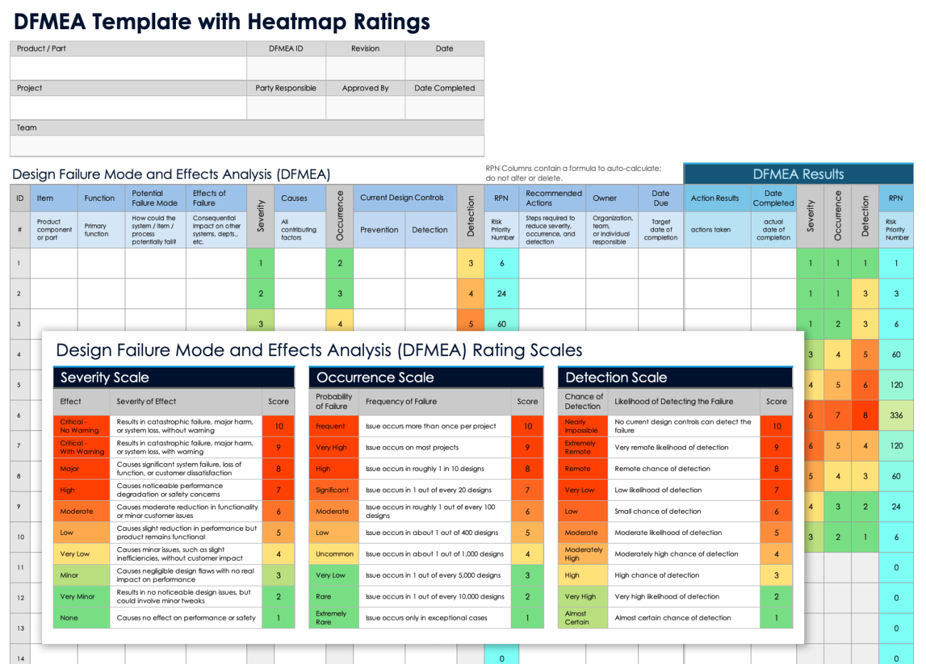
Your Turn: Perform a Mini-DFMEA (15 minutes)
Let's put this into practice on your independent project. This exercise will walk you through the core loop of a DFMEA.
- Select a Function: Choose one critical function of your design. (e.g., "Securely clamp the workpiece," "Support the main shaft," "Transmit torque from motor to output").
- Brainstorm: In a simple text document or on paper, fill out the following, using the template image above as a guide:
- Potential Failure Mode: How could this function fail? (e.g., "Clamp loses grip over time," "Shaft deflects under load," "Belt slips on pulley").
- Potential Effect(s) of Failure: What is the consequence if this failure happens? (e.g., "Workpiece flies out, posing a safety hazard," "Inaccurate positioning of the mechanism," "Loss of power transmission, device stops working").
- Potential Cause(s) of Failure: What is the root design reason for this failure? (e.g., "Incorrect material specified for clamp spring leading to fatigue," "Shaft diameter is too small for the applied load," "Insufficient belt tension specified").
- Rate and Prioritize:
- Assign S, O, D Scores: Using the rating scales in the DFMEA template image, assign a score from 1-10 for Severity, Occurrence, and Detection. These are estimates, but base them on your engineering judgment.
- Calculate RPN: Multiply the three scores:
RPN = S × O × D. - Recommended Action: Based on the high scores (especially Severity) and the RPN, what is one action you could take to improve the design? (e.g., "Perform FEA on the clamp to verify stress levels," "Increase shaft diameter," "Add a belt tensioning feature to the design").
This simple exercise is the heart of risk management in product design.
Conclusion
Today you've added two powerful, industry-standard methodologies to your engineering toolkit. These move your design process beyond just function and form into the critical domains of cost, manufacturability, and reliability.
Key Takeaways:
- DFMA is a proactive approach to designing parts and assemblies that are easy and cost-effective to produce. Simple rules, like reducing part count and designing for your manufacturing process, have a huge impact.
- FMEA is a structured risk assessment tool to identify and mitigate potential design failures before they happen.
- The RPN (S x O x D) is a key metric used to prioritize which risks to address first. High Severity should always be a primary focus.
- Both DFMA and FMEA are formal, documented processes that are highly valued in industry and make for excellent portfolio content. They show you think like a professional engineer.

Preview of the Next Lesson:
With these analyses complete, your design is becoming more robust and well-defined. The next step is to formally communicate all of this design intent to a manufacturer. In our next lesson, we will begin the final phase of documentation by learning how to create a complete drawing package for the independent project, including assembly, sub-assembly, and detailed part drawings. The critical features you've identified through tolerance analysis, DFMA, and FMEA will be the focus of these drawings.