Hello! Welcome to our second-to-last lesson in this course.
In our previous session, you learned how to write a compelling, high-level technical summary for your portfolio projects using the "Inverted Pyramid" structure. That summary is the story you tell a recruiter or hiring manager to get them interested.
Today, we're building the evidence locker. This lesson focuses on the learning outcome: Curate key calculations and analysis reports to create a technical appendix for each project. This appendix is the deep-dive proof that you provide for the technical hiring manager or senior engineer who wants to see the rigor behind your claims. It's where you demonstrate that your beautiful CAD models are backed by solid engineering principles.
We will cover what a technical appendix is, how to structure your analysis reports professionally, and best practices for presenting calculations and data to prove your competence.
1. What Belongs in a Technical Appendix?
Think of the appendix as the "behind-the-scenes" documentation. While your main portfolio page shows the polished final design, the appendix shows the engineering work that got you there. Its purpose is to hold detailed information that would otherwise clutter your main project summary.
So, what kind of documents should you curate for it?
Engineering Documentation Explained (ISO)
First, let's formally define what a 'calculation sheet' or analysis report is within the world of professional engineering documentation. The video 'Engineering Documentation Explained (ISO)' by Newtonian World touches on this.
Please watch the short clip from 07:00 to 07:32. The narrator defines a 'calculation sheet' according to ISO standards.
As the video states, a calculation sheet is a formal document providing the results of calculations for essential product characteristics. This includes your hand calculations, FEA reports, and other analyses.
A more comprehensive guide offers other examples of what's suitable for an appendix.
GUIDE FOR WRITING TECHNICAL REPORTS
The 'GUIDE FOR WRITING TECHNICAL REPORTS' from the University of KwaZulu-Natal clearly defines the role of appendices.
Please read section 3.14 Appendices. It provides excellent examples of content that belongs in an appendix, such as sample calculations, lists of data, and commercial data sheets.
Based on these resources, your project appendix should be a curated collection of mini-reports on topics like:
- Sizing calculations (e.g., lead screw, motor, bearings)
- Hand calculations for stress and deflection
- FEA report summaries (setup, key results, validation)
- Tolerance stack-up analyses
- Failure Mode and Effects Analysis (FMEA) tables
- Material or component trade study matrices
The key word is curate. You don't need to include every single calculation. Select the ones that are most critical to the design's success and best demonstrate your engineering skills.
2. How to Structure an Analysis Report
To make your appendix look professional, each piece of analysis should be presented as a concise, standalone mini-report. You don't need to write a 20-page document, but adopting a standard structure shows discipline and makes your work easy to follow.
The NASA guide for stress analysis reports provides an industry-leading template we can adapt.
PREPARATION OF STRESS ANALYSIS REPORTS 8594001
We will use the NASA document 'PREPARATION OF STRESS ANALYSIS REPORTS' as our gold standard for structure. While your portfolio appendix won't need this level of formality, following its structure shows you know what professional analysis documentation looks like.
Please review the overall structure in Figure 1 on page 4. Then, quickly read the descriptions for the following sections to understand their purpose: 3.0 INTRODUCTION 4.0 MATERIAL PROPERTIES & ALLOWABLES SUMMARY 6.0 LOADS SUMMARY 7.0 CALCULATIONS (Pay special attention to the distinction between Hand Calculations and Computer Analyses) 9.0 APPENDIX (Note the examples of what goes into an appendix of a formal report)
Let's adapt this NASA structure for one of your curated analysis reports (e.g., the FEA of a bracket):
- Objective: A one-sentence statement. (e.g., "To verify that the motor mounting bracket withstands the maximum operational torque with a factor of safety > 3.0.")
- Inputs: A simple list or table.
- Material: e.g., 6061-T6 Aluminum (Yield Strength = 276 MPa)
- Loads: e.g., Max Torque = 15 Nm; Bolt Preload = 5 kN
- Constraints: e.g., Fixed geometry at bolt holes.
- Analysis & Results: This is the core.
- Hand Calculation: Show a simplified check (e.g., treating a feature as a simple cantilever beam). This proves you can sanity-check your results.
- FEA: Include screenshots of your mesh, loads, constraints, and result plots (stress, displacement, factor of safety). Always label the plots clearly with max/min values.
- Conclusion: A one-sentence summary. (e.g., "The FEA shows a minimum factor of safety of 4.2, which meets the design requirement. Hand calculations for the primary failure mode are within 15% of FEA results, providing confidence in the model.")
Here is a perfect visual example of combining FEA with hand calculations for verification, just as described in the NASA guide.

3. Best Practices for Presenting Calculations
Clarity is paramount. An engineer reading your calculations should be able to follow your logic without having to guess.
The UKZN guide provides an excellent checklist for this.
GUIDE FOR WRITING TECHNICAL REPORTS
Let's dive into the specifics of formatting your calculations. The UKZN guide has a dedicated appendix just for this.
Please read APPENDIX C: GUIDELINES FOR THE DOCUMENATION OF DERIVATIONS AND CALCULATIONS. Focus on sections C.3 (Sample calculations), C.5 (Layout of equations), and C.6 (Traceability).
Here are the most critical takeaways for your portfolio:
- Traceability: Always cite your sources for formulas (e.g., "Shigley's Mechanical Engineering Design, Eq. 8-1") and material properties. This is a hallmark of a professional engineer.
- Show Your Work: For any calculation, present it in three steps:
- The formula in symbols:
- The formula with values substituted:
- The final answer with units:
- Be Consistent with Units: Use SI units wherever possible. Clearly label all numbers.
- Use an Equation Editor: Hand-written equations in a scanned document are acceptable, but for a truly polished look, use a tool like Microsoft Equation Editor, or the LaTeX format used above, to type your equations.
Test your understanding!
Imagine you are creating a mini-report for the lead screw sizing calculation from Project 1. Based on the NASA and UKZN guidelines, list the five main sections you would create for this report and write one sentence describing the content of each.
Show answer
Here is an example structure for the lead screw sizing calculation report:
- Objective: To determine the required lead screw diameter to prevent buckling under a maximum axial load of 500 N.
- Inputs: List key parameters like Axial Load (500 N), Screw Length (300 mm), End Support Condition (e.g., Fixed-Free), and Material (e.g., Steel, E = 200 GPa).
- Analysis & Results: State the formula used (e.g., Euler's critical load formula, ), show the calculation with substituted values, and state the resulting minimum required diameter.
- Component Selection: State the selected off-the-shelf lead screw that meets or exceeds the calculated requirement (e.g., "Selected 10mm diameter lead screw from McMaster-Carr, P/N XXXX").
- Conclusion: The selected 10mm diameter lead screw provides a factor of safety of 2.5 against buckling, meeting the design requirements.
4. Curating Other Analysis Reports
Your engineering process involves more than just stress analysis. Including other types of reports showcases the breadth of your skills. Two great examples are FMEA and Tolerance Stack-ups. You don't need to write a narrative for these; the completed table or spreadsheet itself is the report.
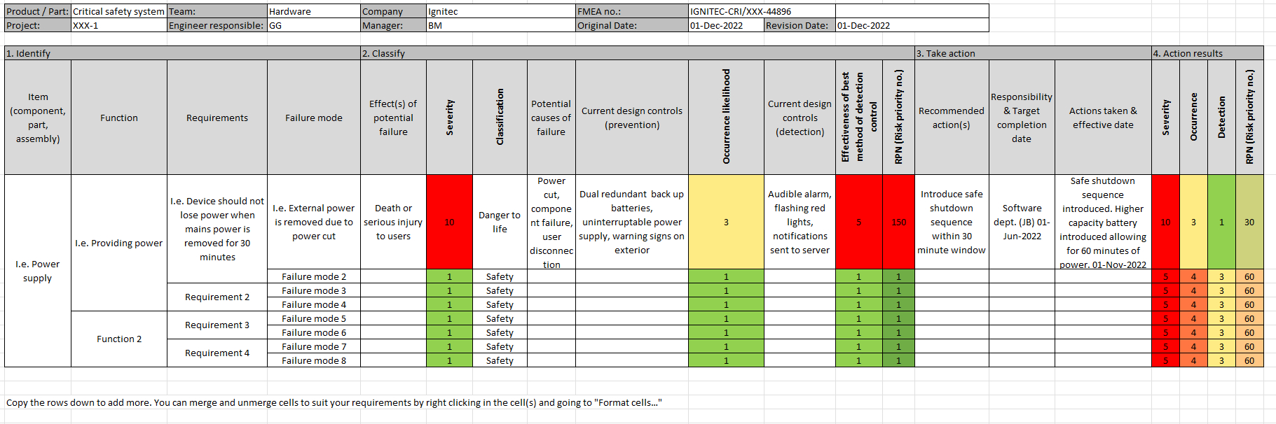
Including a well-documented FMEA or a tolerance analysis for a critical interface in your appendix is a fantastic way to show that you think about the entire product lifecycle, from design to manufacturing and reliability.
Conclusion
You are now equipped to build the technical foundation of your portfolio. The appendix is where you prove your engineering claims, demonstrating not only that you can get the right answer, but that you follow a disciplined, professional process to do so.
Key Takeaways:
- The Appendix is Your Proof: It contains the detailed calculations and analysis reports that support the claims in your project summary.
- Structure is Professionalism: Use an industry-standard format (like the adapted NASA structure) for your mini-reports to show discipline.
- Clarity is King: Present calculations clearly with formulas, substituted values, and results with units. Always cite your sources.
- Curate, Don't Dump: Select the most critical analyses (e.g., stress, FMEA, tolerance stacks) that best demonstrate your problem-solving skills for the project.
Preview of the Next Lesson:
This is the moment we've been building towards! In our final lesson of the course, "Compile all three projects into a professional portfolio document with supporting visuals and narratives," you will bring everything together. You'll combine the project summaries from the last lesson with the appendix content from this one, add visuals, and assemble the final, polished portfolio document that you can confidently show to employers.