Hello! Welcome to the first lesson in our new module, "Detail Design and Tolerance Application."
In the last module, you did an excellent job verifying the structural integrity of a component from your linear actuator project. You've proven that the part is strong enough to handle its operational loads. Now, we shift our focus from "Will it break?" to a question that is just as important in real-world engineering: "Will it fit?"
Parts are never manufactured to their exact nominal dimensions; there is always some variation. Managing this variation is the key to creating products that can be assembled reliably and function correctly. This is the essence of dimensioning and tolerancing.
Today, we'll tackle the first and most fundamental step in this process. Your learning outcome is to identify critical dimensions and interfaces requiring tight tolerances in an assembly. This skill forms the foundation for creating professional engineering drawings and ensures that your design intent is successfully translated into a physical product.
1. From Individual Parts to Functional Assemblies
As an engineer, your focus is rarely on a single part in isolation. The real value comes from how parts interact within an assembly to perform a function. Traditional dimensioning on a part drawing tells you the size and shape of that part, but it doesn't inherently guarantee it will work correctly with others.
Let's start with a short video that introduces this core concept and sets the stage for why we need a more systematic way of thinking about dimensions.
This video, "What is GD&T in 10 Minutes" from Straight To The Point Engineering, provides an excellent high-level overview. We'll watch a few key sections.
Please watch two segments: From 0:25 to 2:48: This part explains why we must think at the assembly level. From 5:18 to 8:05: This part shows a practical example. Pay close attention to how the narrator identifies the "critical assembly feature" (the boss and bore) and the "interface or mating surfaces." These are the exact kinds of features we are learning to identify today.
The video makes a crucial point: our goal is to guarantee fit and function at the assembly level. To do this, we can't treat all dimensions equally. We must first identify the ones that are critical.
2. What Makes a Dimension or Interface "Critical"?
A critical dimension is any dimension that directly influences a functional requirement of the assembly. A critical interface is a surface or feature on a part that directly contacts or interacts with another part.
Think of it like this: in your FEA work, you learned to focus on areas of high stress. In tolerance analysis, we focus on areas of high interaction.
These critical areas typically fall into a few categories:
- Mating Surfaces: Where two parts touch.
- Bearing Surfaces: Where parts slide or rotate against each other.
- Sealing Surfaces: Where a seal (like an O-ring) must be compressed.
- Alignment Features: Features like pins and holes used to precisely locate parts relative to each other.
The following resource provides a simple and effective checklist for identifying these areas.
Understanding Mechanical Engineering Tolerances for Holes and Shafts
The article "Understanding Mechanical Engineering Tolerances for Holes and Shafts" from Blackrock Engineering has a great section that summarizes this concept perfectly.
Please read the section titled "The 80/20 Rule for Tolerances." This section provides a concise list of what constitutes "Critical Areas" versus "Non-Critical Areas."
This "80/20 rule" is a practical guiding principle used by many design engineers. Your most detailed analysis and tightest tolerances should be reserved for that critical 20% of features that govern the assembly's function.
This image provides a clear visual of this concept, distinguishing between features that are essential for function and those that are not.

3. A Systematic Method: Tracing the Tolerance Chain
Identifying critical features visually is a good start, but for complex assemblies, we need a more rigorous method. This is where the concept of a tolerance chain (or tolerance stack) comes in.
A tolerance chain is the sequence of dimensions—often across multiple parts—that add up to create a critical assembly gap or fit. To identify critical dimensions, you first need to identify the critical assembly requirement and then trace the dimensional path that controls it.
Building Tolerance Chains and Loop Diagrams: A Practical Guide ...
The article "Building Tolerance Chains and Loop Diagrams" from Blackrock Engineering provides an excellent, industry-focused guide on this process. We will focus on the first step of this method.
Please read the section "Step 1: Identify Critical Dimensions." Pay close attention to the "Questions to Ask" under the Functional, Manufacturing, and Quality headings. These questions are your primary tool for pinpointing what's critical in any design.
Let's summarize those key questions:
- Function: What must this assembly do? (e.g., "A shaft must spin freely in a housing.") What happens if a gap is too big or too small?
- Assembly: How do these parts go together? Is there a required clearance for a tool or hand?
- Manufacturing: Can this be made? Can it be measured for quality control?
By asking these questions, you force yourself to think through the entire lifecycle of the product, which is a hallmark of a seasoned engineer.
Failing to properly identify and dimension these critical features is a common source of costly errors, as shown in the image below.
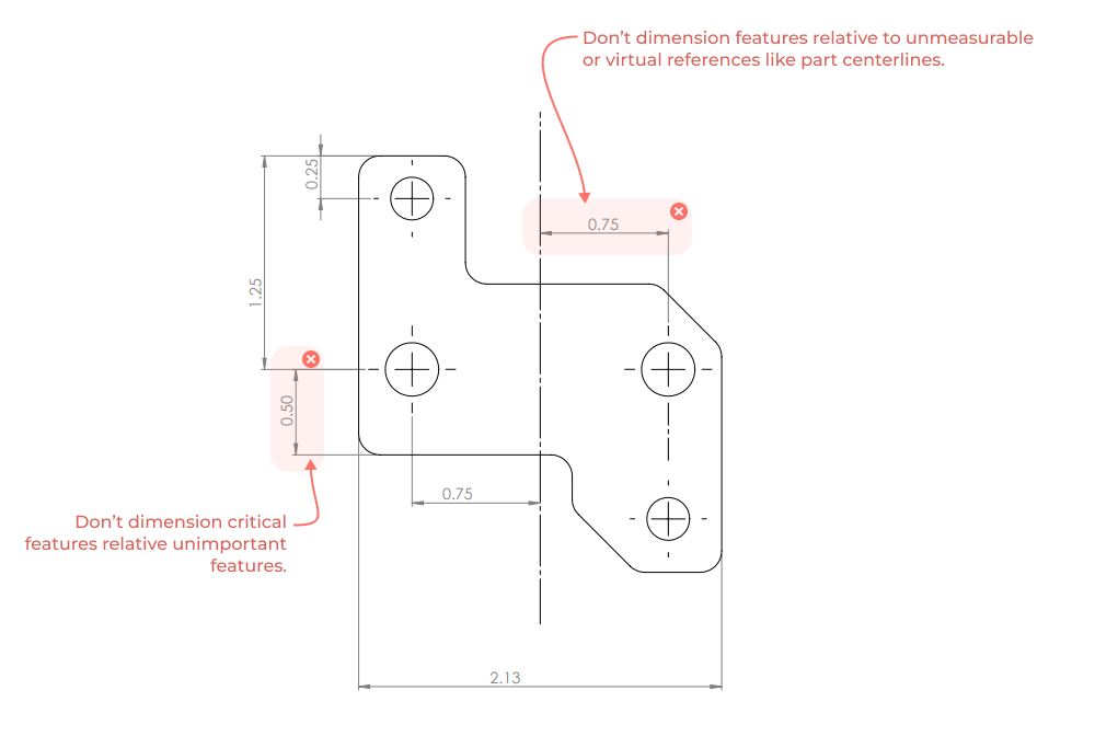
4. Why Identification Is Crucial: An Example
To see why tracing the correct dimensional path is so important, let's look at a simple example of how individual tolerances can accumulate—or "stack up"—to affect a critical clearance.
Tolerance Stackup: Simple Assembly
This video, "Tolerance Stackup: Simple Assembly" by R. Dean Odell, clearly demonstrates the concept.
Please watch from 1:12 to 5:40. You don't need to follow every number in the calculation. Instead, focus on two key moments: At 3:20: Notice how simply adding up the tolerances of all the individual dimensions in the chain results in a potential interference. At 4:26: This is the most important part. See how by changing the dimensioning scheme—essentially, by redefining the tolerance chain to be more direct—the total variation is reduced significantly, without making any single tolerance tighter.
This video powerfully illustrates our main point: correctly identifying the chain of dimensions that controls a critical function is the most important step. A poor dimensioning scheme can create assembly problems even when every individual part is within its own tolerance.
Test your understanding!
Imagine you are designing a simple bookshelf. The total width of the opening is 900 mm. You want to place three vertical dividers inside, creating four equal sections for books.
What is the single most critical assembly-level requirement you need to analyze? And which part dimensions would form the tolerance chain that controls this requirement?
Show answer
The most critical requirement is ensuring that the three dividers will actually fit inside the 900 mm opening with some clearance.
The tolerance chain would consist of:
- The width of the main bookshelf opening (e.g.,
900 ± 1.0 mm). - The thickness of the first divider (e.g.,
18 ± 0.5 mm). - The thickness of the second divider (
18 ± 0.5 mm). - The thickness of the third divider (
18 ± 0.5 mm).
The "critical gap" is the remaining space after the three dividers are placed inside the main opening. The dimensions in the chain are the ones you must identify and control.
Conclusion
In this lesson, we've established the crucial first step in creating robust, manufacturable designs. You've learned to look beyond individual parts and focus on the interfaces and dimensional chains that govern the function of a complete assembly.
Key Takeaways:
- Not all dimensions are equal. Critical dimensions are those that directly affect an assembly's fit, function, or manufacturability.
- Critical features are typically found at mating surfaces, interfaces, and alignment features.
- The "80/20 Rule" is a practical guide: apply your focus and tightest tolerances to the 20% of features that do 80% of the functional work.
- A tolerance chain is a systematic tool for tracing the dimensional path that controls a critical assembly requirement (like a gap or fit).
Preview of the Next Lesson:
Now that you know how to identify a critical tolerance chain, the logical next step is to perform the math. In our next lesson, you will learn how to perform a worst-case tolerance stack-up analysis for a critical assembly interface. This will allow you to calculate, with certainty, whether your parts will always fit together under all manufacturing conditions.