Hello! Welcome back to our work on creating professional engineering designs.
In our last lesson, we established a systematic way to select tolerances by linking the functional requirements of a part to the capabilities and costs of various manufacturing processes using IT grades. We answered the question of how precise a dimension needs to be.
Today, we address the next level of detail that a design engineer must control. A part's function is determined by more than just its size and shape; its surface properties are equally critical. This lesson tackles the learning outcome: Specify material treatments and surface finishes on drawings. You will learn how to control the texture of a surface for things like seals and bearings, and how to specify treatments that alter a material's fundamental properties, such as hardness and corrosion resistance.
This is a vital skill that separates a basic model from a fully-defined, manufacturable component, and it's something you'll use constantly in professional practice.
1. Beyond Dimensions: An Introduction to Surface Finish
The term "surface finish" or "surface texture" refers to the fine-scale variations on a part's surface. As a mechanical engineer, you know that no surface is perfectly smooth. These imperfections, left by the manufacturing process, can have a huge impact on friction, wear, fatigue life, and the ability of a surface to form a seal.
A surface's texture is generally broken down into three components:
- Roughness: The finest-scale, high-frequency variations, like microscopic hills and valleys.
- Waviness: A more gently undulating, longer-wavelength variation, often caused by machine chatter or vibration.
- Lay: The dominant direction or pattern of the surface texture, left by the cutting tool or grinding wheel.
To get a solid grasp of these concepts and the most common parameters used to quantify them, please read the first few sections of the following article.
The article "The Basics of Surface Finish" from GD&T Basics provides an excellent introduction to these concepts. It clearly defines roughness, waviness, and lay, and explains the two most common roughness parameters, Ra and Rz.
Please read from the beginning of the article down to the end of the "Roughness Parameters & Calculations" section. Focus on understanding: The visual difference between roughness, waviness, and lay. The definition of Ra (Average Roughness) and Rz (Mean Roughness Depth) and why Rz is typically a larger value for the same surface.
2. Specifying Surface Finish on Engineering Drawings
Knowing what surface finish is doesn't help unless you can communicate your requirements to a manufacturer. This is done using a standardized symbol, often called a "surface texture symbol" or simply a "finish symbol." While the basic symbol looks like a check mark, its annotations carry a lot of information.

The chart above gives you a great overview of the ASME standard, which is widely used in the US. To see how these symbols are constructed and interpreted in detail, particularly according to the international ISO standard, the following video is an excellent guide.
Indication of surface texture tolerances on technical drawings [ENGLISH]
The video "Indication of surface texture tolerances on technical drawings" provides a deep dive into the ISO 1302 standard. It explains the meaning of each part of the symbol and shows how to place it on a drawing.
Please watch from 3:20 to 4:50 and from 6:45 to 8:44. The first segment covers the placement of information around the root symbol. The second segment details material removal requirements, lay symbols, and how to place the symbol on a drawing.
As you saw, you can specify:
- Roughness Value: The number (e.g.,
Ra 1.6) is the most common callout. - Material Removal: The symbol can indicate if material removal is required (machining), prohibited (as-cast/forged), or optional.
- Lay: A symbol indicating the direction of the tool marks (e.g., perpendicular, parallel, multi-directional).
- Other Parameters: You can also specify waviness, sampling length, or other less common parameters.
Just as with tolerances, the key is to specify surface finish only where it's functionally necessary. Common areas include:
- Shaft surfaces that will run in a bearing or bushing.
- Faces that require a gasket or o-ring seal.
- Sliding surfaces that experience wear.
3. Connecting Surface Finish to Manufacturing and Cost
This is where our last lesson on tolerances connects directly to today's topic. The surface finish a process can achieve is inherently linked to its precision and cost. A rough milling operation will produce a much rougher surface than a precision grinding operation.
Specifying a very smooth finish (a low Ra value) will often force the use of secondary processes like grinding, lapping, or polishing, which dramatically increases cost. Your job as a designer is to select a finish that meets the functional need without being unnecessarily expensive.
Let's return to the "The Basics of Surface Finish" article to look at a chart that connects manufacturing processes to achievable surface roughness.
Please find the section titled "Practical Considerations" and study the chart (Figure 9) that shows the range of average roughness (Ra) produced by common manufacturing processes. This is a crucial reference for a design engineer.
Test your understanding!
You are designing a steel axle with a nominal diameter of 25 mm. One section of the axle needs to sit inside a press-fit ball bearing.
- Why is the surface finish on this section of the axle critical?
- Looking at the "Average Roughness produced by common manufacturing processes" chart, you see that standard turning can produce a finish of around Ra 1.6 - 6.3 µm. A bearing manufacturer's handbook recommends a finish of Ra 0.8 µm for this application. What is the implication for your manufacturing plan and the part's cost?
- How would you notate a requirement for an average roughness of 0.8 µm, where machining is required and the lay should be perpendicular to the view shown on the drawing? (You can describe the symbol or sketch it out).
Show answer
- The surface finish is critical because it affects the quality of the press-fit. A surface that is too rough could be damaged during assembly and may not provide the consistent interference needed for a secure fit. It can also create stress concentrations that reduce fatigue life.
- The implication is that standard CNC turning is likely insufficient to meet the Ra 0.8 µm requirement reliably. You would need to add a secondary grinding operation for that surface. This increases the number of manufacturing steps, complexity, and therefore, the cost of the part.
- The notation would be:
- A basic check-mark symbol with a horizontal line across the top.
- A circle in the V-junction of the check mark to indicate that material removal is required.
- The value
Ra 0.8would be placed just above the horizontal line. - A symbol consisting of two short parallel lines, one on top of the other and rotated 90 degrees (⊥), would be placed to the right of the check mark to indicate a perpendicular lay.
4. Specifying Material Treatments
We've covered surface texture, but what about surface properties? Material treatments are processes that alter the surface of a part to improve its hardness, wear resistance, corrosion resistance, or appearance.
Examples include:
- Case Hardening: Hardening the outer layer of a steel part while keeping the core ductile.
- Anodizing: A common treatment for aluminum that creates a hard, corrosion-resistant oxide layer.
- Plating: Applying a thin layer of another metal (like chrome or zinc).
- Painting/Powder Coating: Applying a protective and decorative coating.
Unlike surface finish, these are almost always specified using a note on the drawing. The note should be clear and reference an industry standard where applicable. Let's look at a common example: anodizing aluminum.
How to Design and Manufacture Anodized Aluminum Parts
The article "How to Design and Manufacture Anodized Aluminum Parts" is a practical guide written for design engineers. It covers what anodizing is, the different types, and how to specify it.
Please read the following three sections: "What is Anodizing and Why Use It?" to understand the basic process. "Types of Anodizing and Relevant Standards" to learn about Type I, II, and III and the MIL-A-8625 standard. "Working with Anodizing vendors..." to see a direct example of how to call out an anodizing requirement on an engineering drawing.
As the article shows, a proper callout for anodizing includes:
- The relevant standard (e.g., MIL-A-8625).
- The Type (e.g., Type II for cosmetic or Type III for hardcoat).
- The Class (Class 1 for non-dyed, Class 2 for colored).
- Any special instructions, such as masking for threaded holes or critical surfaces where the coating buildup is not desired.
5. Bringing It All Together on a Drawing
Let's look at a professional drawing that combines many of the elements we've discussed.
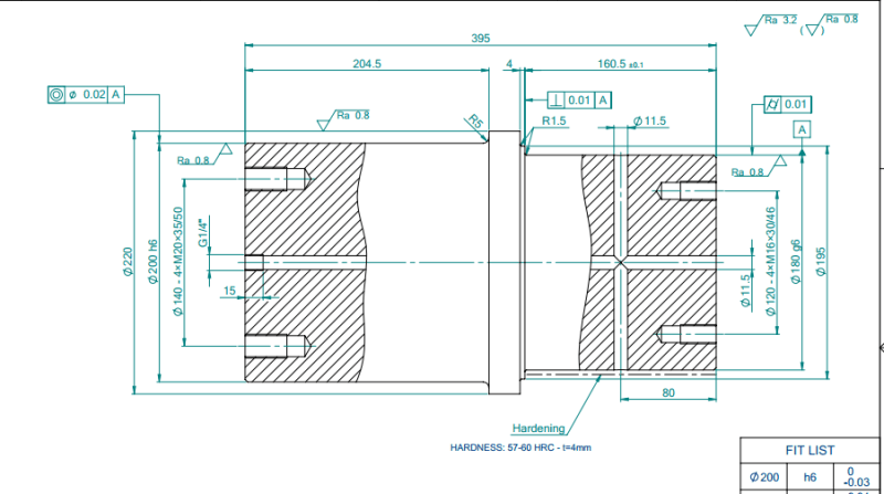
Take a moment to examine this drawing. You can see:
- Surface Finish Symbols: Notice the
Ra 1.6andRa 0.8callouts on different diameters. The designer has specified a smoother (and more expensive) finish only on the surfaces that likely interact with bearings or seals. - Material Treatment Note: In the top left, there is a clear note for "HARDENING". It specifies the required hardness range (57-60 HRC) and the case depth (t=4mm), which is the thickness of the hardened layer.
This single example effectively demonstrates how a designer uses different tools—dimensions, tolerances, surface finish symbols, and notes—to fully and unambiguously define a component.
Conclusion
In this lesson, you've added two powerful specification tools to your engineering toolkit. You now have a framework for thinking about and controlling the surface characteristics of your designs.
Key Takeaways:
- Surface finish (roughness, waviness, lay) is critical for controlling friction, wear, and sealing. It is specified on drawings using the standardized surface texture symbol.
- Material treatments (hardening, anodizing, plating) alter the physical properties of a part's surface. They are specified using clear, detailed notes that often reference industry standards (e.g., MIL-A-8625, HRC values).
- Both specifications have a direct and significant impact on manufacturing processes and cost. A designer's goal is to apply them only where functionally necessary.
Preview of the Next Lesson:
We have now assembled all the individual components of a detailed drawing: dimensions, GD&T, tolerance values, surface finishes, and material treatments. In our next lesson, we will put it all together and create detailed drawings for critical components from our project, applying these specifications in the OnShape environment.