Hello! Welcome to the first lesson of Module 6.
In the previous module, we covered the essential theories and practices of detail design. You learned how to establish datum reference frames, apply various GD&T controls, and specify tolerances and finishes to create unambiguous engineering drawings.
Today, we shift from theory to practice. We will begin the finalization of Project 1, the linear motion system. This lesson directly addresses the learning outcome: Apply GD&T and refined dimensions to the Project 1 detailed drawings. You will take the components you've modeled and begin the process of creating the professional, detailed documentation that forms the core of a portfolio piece. This is where your design intent is formally communicated to manufacturing and inspection.
1. Tolerancing with Intent: The 'Why' Behind the Symbols
Before jumping into Onshape, it's crucial to reinforce the mindset behind effective tolerancing. Simply adding tighter tolerances or more GD&T symbols doesn't automatically make a design better. In fact, it can make it much more expensive and difficult to produce. The goal is to apply tolerances that are as loose as possible while still ensuring function.
This practical trade-off between cost, manufacturability, and performance is a daily reality for a design engineer. The following video provides an excellent perspective on this.
Tolerances Didn’t Make Sense Until I Learned This
The video "Tolerances Didn’t Make Sense Until I Learned This" by Engineering Gone Wild offers a great real-world perspective on why thoughtful tolerancing is critical. It clears up common misconceptions and frames tolerancing as a functional and economic decision.
Please watch the following segments: 1:12 - 3:08: Focus on the definition of tolerance and the critical mistake of over-tolerancing. Pay attention to the discussion on cost, lead times, and the importance of thinking functionally. 3:33 - 4:10: This part contrasts traditional dimensional tolerancing with GD&T, highlighting the inefficiency of a square tolerance zone for a round feature. 10:04 - 10:54: This segment briefly covers the Position tolerance and summarizes how GD&T provides manufacturing flexibility while maintaining function.
As you can see, the core idea is to use tolerances to control the aspects of the part that are critical to function, and to do so in a way that provides the manufacturer with the largest possible room for error. GD&T is the ideal language for this.
2. A Strategic Approach for Your Linear Actuator
Let's apply this thinking to your linear motion system project. Before adding a single dimension, you should identify the critical features and interfaces that determine if the assembly will work correctly.
Consider a part like one of your mounting brackets (e.g., for the motor or a guide rail support). Here are the key functional relationships to consider:
- Mounting Face: The surface that bolts to the main frame must be flat to ensure stability and prevent rocking.
- Component Face: The surface where the guide rail or motor mounts must be parallel to the main mounting face to ensure proper alignment of the linear motion path.
- Hole Pattern: The holes used to mount the component must be in the correct location relative to each other and to the edges of the part so that bolts will pass through freely and align with the mating component.
This thought process leads us to a clear tolerancing strategy. For that mounting bracket, a logical Datum Reference Frame (DRF) would be:
- Datum A (Primary): The main mounting face. This constrains 3 degrees of freedom (one translation, two rotations) and represents the surface it's bolted against.
- Datum B (Secondary): A long, stable edge of the part. This constrains 2 more degrees of freedom (one translation, one rotation).
- Datum C (Tertiary): An edge perpendicular to Datum B. This constrains the final degree of freedom.
With this DRF, you can now control other features relative to it. For example, you can apply a Parallelism tolerance to the component mounting face relative to Datum A. You can use a Position tolerance to control the location of the mounting holes relative to Datums A, B, and C.
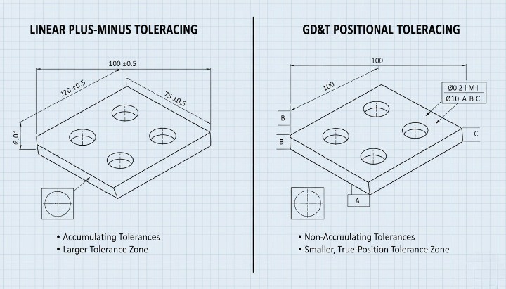
The image above clearly shows why a GD&T Position tolerance is superior for your mounting holes. It provides a larger, more functional (circular) tolerance zone and avoids the tolerance accumulation that can happen with a chain of linear dimensions.
3. Practical Application: Detailing a Critical Component
Now it's time to apply these concepts in Onshape. Open your Project 1 Onshape document and create a new drawing for one of your critical components, such as a motor mount, a bearing block support, or a lead screw nut bracket. Place the necessary orthographic views (Front, Top, Right) and an isometric view.
The following guide will walk you through the exact steps to add Datums and Feature Control Frames in Onshape. Use your own part as the subject of the exercise.
We will now use a section from the "Week 5: 2D Drawings" guide we've referenced before. It provides a perfect, step-by-step tutorial for applying datums and GD&T callouts to a bracket-like part in Onshape. Follow these instructions on your own drawing.
Please read and follow the exercise in the section titled "Geometric Dimensioning & Tolerancing In-Class Exercise #5". It will guide you through: Creating Datums: Apply datum feature symbols to establish your DRF (Datum A, B, C). Applying a Parallelism callout: To control the orientation between two surfaces. Applying a Position tolerance: To control the location of a hole pattern. This involves first converting the locating dimensions to Basic dimensions.
Test your understanding!
In the exercise you just completed, the Position tolerance for the two small holes was Ø.005 with respect to Datums A and B. What does this mean in plain English? Why is it better than the original +/- .005 linear tolerances?
Show answer
It means the central axis of each manufactured hole must lie within a perfect cylindrical tolerance zone that is 0.005 inches in diameter. The position and orientation of this cylindrical zone are locked in by Datums A and B.
This is better because it provides 57% more tolerance area than the +/- .005 square zone, giving the manufacturer more room for error where it doesn't affect function (in the corners of the square). It also directly controls the location relative to the functional datums, preventing tolerance stack-up issues.
4. Refining Dimensional Tolerances
The learning outcome also requires you to apply refined dimensions. This goes beyond just GD&T. It means making conscious decisions about the precision of every dimension on your drawing.
Your drawing's title block contains a set of general tolerances based on the number of decimal places.
X.X= ± 0.03 inX.XX= ± 0.010 inX.XXX= ± 0.005 in
For non-critical features, like the overall outside dimensions of a bracket, relying on these general tolerances is perfectly fine and cost-effective. However, for features critical to fit or function, you must apply an explicit tolerance.
This next resource shows you exactly how to do this in Onshape.
Let's return to the "Week 5: 2D Drawings" guide. The section on tolerances explains how to override the general title block tolerances for critical dimensions.
Please read the subsection titled "Tolerances" (steps 12 through 17). Focus on: How changing the precision (number of decimal places) of a dimension changes its implied tolerance. How to apply an explicit Symmetric tolerance to tighten the control on a critical feature like a keyway.
Now, review the dimensions on your drawing and ask yourself:
- Which dimensions control the fit with a bearing, shaft, or other standard part? These likely need an explicit tolerance (Symmetric, Deviation, or Limits).
- Which dimensions can be left to the general tolerance block without affecting assembly or function?
- Have I used the correct number of decimal places to communicate the required precision for each feature?
Applying this level of thought to your drawings is what separates a beginner's CAD model from a professional engineering deliverable.

Conclusion
In this lesson, you began the crucial process of documenting your design for manufacturing. This is a significant step toward creating a project for your portfolio that demonstrates a professional engineering workflow.
Key Takeaways:
- Effective tolerancing is a strategic process focused on controlling critical-to-function features.
- The first step is to identify functional interfaces and establish a logical Datum Reference Frame (DRF).
- GD&T callouts (like Position and Parallelism) are applied in Onshape using Basic dimensions and the Geometric Tolerance tool.
- Refined dimensions involve consciously deciding whether to use general title block tolerances or apply explicit tolerances to control critical fits.
Preview of the Next Lesson:
With the critical components detailed, our next step is to document the assembly itself. In the next lesson, you will Finalize the top-level assembly drawing for Project 1 with an updated Bill of Materials (BOM). This will involve creating exploded views and ensuring all parts are correctly itemized.