Welcome to your first lesson! The goal of this course is to help you build a portfolio of mechanical design projects that simulate a real-world engineering workflow. We'll be using Onshape, a powerful, cloud-based CAD platform, from start to finish.
Today, we'll begin with the absolute fundamentals. This lesson is designed to help you navigate the Onshape user interface, including the document toolbar, feature list, and view manipulation tools. Mastering the UI is the essential first step before we can dive into designing and modeling. By the end of this hour, you'll be comfortable finding your way around the Onshape environment, setting the stage for all the modeling work to come.
1. Getting Started: Your Onshape Account
Unlike traditional desktop CAD software that requires installation, Onshape runs entirely in your web browser. This means your first step is to create a free account.
Week 1: Introduction to Onshape - “Getting Started”
This guide will walk you through creating a free Onshape Education account, which gives you full functionality. It will also introduce you to the 'Documents' page, which is your main hub for all projects.
Please read the sections 'Getting Started' and 'The Documents Page'. Follow the steps to create your account. I recommend signing up for the free Education Plan as suggested. Once you're signed in, take a moment to look at the Documents page layout.
Once your account is set up, let's create the first document for our course projects. On the Documents page, click the Create button in the top-left corner and select Document. Name your new document "Project 1 - Linear Motion System". This is where we'll eventually build our first full mechanism.
2. A Tour of the Onshape Workspace
With your new document open, you're now in the main Onshape modeling environment, called a Part Studio. It can look a bit empty at first, but it's organized very logically.
To get a quick orientation, let's watch a short guided tour.
Onshape Guided Tour & Beginners Lesson
This video provides an excellent visual tour of the main interface components you'll be using constantly. It's a great way to quickly familiarize yourself with the layout.
Watch the segment from 00:43 to 01:56. Pay close attention to the names and locations of these key areas: the central 'geometry area' with its default planes (Front, Top, Right), the 'Feature list' on the left, and the 'main toolbar' at the top.
As the video showed, the interface is centered around a few key areas. Let's formalize those concepts.
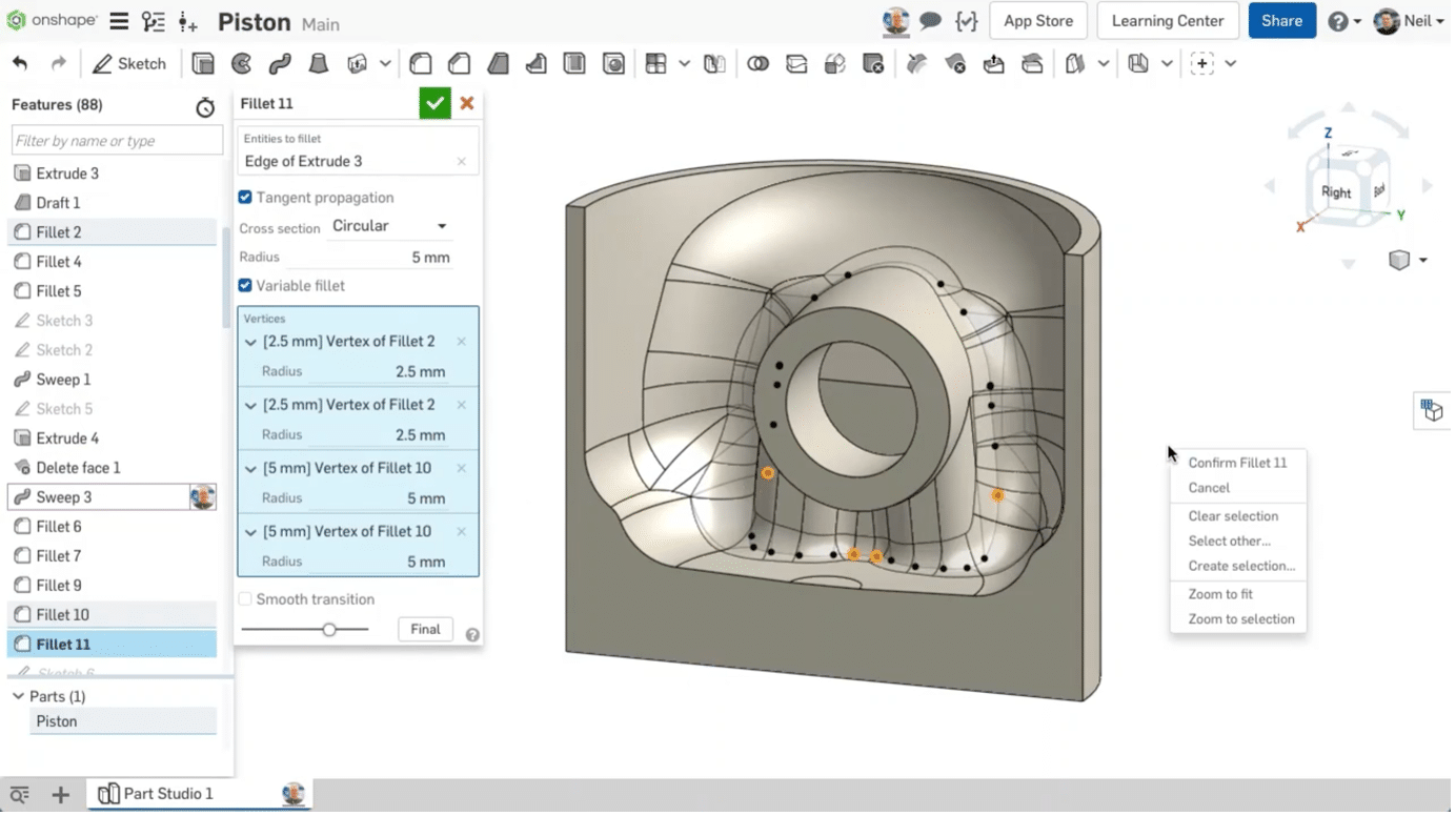
The main components are:
- Graphics Area: The large central space where your 3D model is displayed. It starts with three default planes (Top, Front, Right) and an Origin.
- Feature List: The list on the left side of the screen. This is a chronological history of every action (sketch, extrude, fillet, etc.) you take to build your part. This parametric history is fundamental to modern CAD, as it allows you to go back and edit any step.
- Part List: Located below the Feature List, this shows all the individual solid bodies you have created.
- Toolbar: The row of icons at the top of the screen. This toolbar is context-sensitive, meaning the tools it displays will change depending on what you are doing.
To understand how the toolbars work, please review the official Onshape documentation.
The Onshape Help Center gives a precise breakdown of the different toolbars and the Part Studio interface. Understanding this will help you know where to find the right tools for a given task.
Read the section titled 'Toolbars'. You don't need to memorize every icon, but focus on understanding that there are different toolbars for different environments (e.g., a 'Sketch toolbar' for 2D drawing and a 'Feature toolbar' for 3D modeling).
Test your understanding!
Based on the image of the piston model above, what do you think is the purpose of the Feature List in a professional design process? Why is it more than just a history log?
Show answer
The Feature List serves as the "design recipe" for the part. For a professional engineer, it documents the design intent. By reading the list of features in order, another engineer can understand how the part was constructed and why certain decisions were made. It's also critical for making modifications; instead of starting over, you can go back to a specific feature (e.g., the main extrusion) and change its dimensions, and all subsequent features (like fillets and holes) will automatically update. This is the core of parametric modeling.
3. View Manipulation: Navigating in 3D
Being able to efficiently rotate, pan, and zoom is crucial for productivity in any CAD software. Onshape provides two primary methods for this: the View Cube and mouse controls.
Let's return to the video to see these in action.
Onshape Guided Tour & Beginners Lesson
This final clip from the guided tour demonstrates how to use both the View Cube and your mouse to control the camera in the 3D space.
Watch from 02:05 to 02:37. As you watch, try performing the actions in your own Onshape document. Practice orbiting (right-click + drag), panning (middle-click + drag, or Ctrl + right-click + drag), and zooming (scroll wheel).
The most common controls are:
- Orbit: Hold the right mouse button and drag.
- Pan: Hold the middle mouse button (or scroll wheel) and drag.
- Zoom: Roll the scroll wheel in and out.
- Zoom to Fit: Press the 'F' key to fit all geometry to your screen.
Pro Tip: Customize Your Controls
Since you have experience with other engineering software, you may be accustomed to a different navigation scheme (e.g., from SolidWorks, CATIA, or NX). Onshape allows you to change the mouse controls to match other popular CAD packages. This can dramatically shorten your learning curve.
You can find these settings by clicking on your account name in the top-right corner and selecting "My account", then navigating to the "Preferences" section.

I suggest you take a moment to set your view manipulation preset to a system you're already familiar with. This will make navigation feel much more natural.
Conclusion
In this lesson, we took our first steps into the Onshape environment. You've learned how to:
- Create an account and a new document.
- Identify the key components of the user interface: the Graphics Area, Feature List, Part List, and the context-sensitive Toolbars.
- Navigate your 3D workspace using the View Cube and, more importantly, the mouse controls for orbiting, panning, and zooming.
- Customize your navigation controls to match your preferences.
This foundation is critical. Every subsequent lesson will build on your ability to move around the interface and understand where to find the tools you need.
In our next lesson, we will focus on managing Onshape documents. You'll learn how to organize your files and, most importantly, use Onshape's powerful versioning system. This is a key feature for maintaining a professional workflow and tracking your design history without creating dozens of separate "v1," "v2," "final" files.