Hello! Welcome to the first lesson in our new module, Advanced Mechanical Components and Powertrains.
In our previous module, we finalized our study of Design for Manufacturing and Assembly (DFMA) by learning how to modify designs to minimize material waste. That skill set is crucial for creating cost-effective parts. Now, we shift our focus from individual components to the systems that make them move. Over the next few modules, we will dive into designing the "engine room" of mechanical systems: the powertrain.
Today, we address the learning outcome: Select between a gear train and a belt drive, and calculate required ratios and center distances. This is one of the most fundamental decisions in power transmission. The choice you make here will define your system's performance, cost, complexity, and maintenance requirements. This lesson will equip you to make that choice confidently and perform the initial sizing calculations needed for your project layouts.
1. The Core Decision: Gears vs. Belts
When you need to transmit rotational power from a motor to a mechanism, gear drives and belt drives are two of the most common solutions. Each has distinct advantages and disadvantages that make them suitable for different applications.

To make an informed decision, it's helpful to compare them across several key engineering criteria.
Mechanical Analysis: Belt and chain drives
The following resource provides an excellent, concise table comparing belt, chain, and gear drives. We will focus on the comparison between belt and gear drives.
Please read the table on slide 5, titled 'Belt drives Chain drives Gear drives'. Focus on the columns for 'Belt drives' and 'Gear drives' and compare them on characteristics like Use, Speed, Disadvantage, and Advantage.
Based on this comparison, here is a summary of the primary trade-offs:
| Feature | Gear Drive | Belt Drive | Typical Application |
|---|---|---|---|
| Torque/Power | High torque, high power capacity. | Lower torque capacity (but can be high). | Gears: Vehicle transmissions, heavy machinery. Belts: Engine timing, conveyors, 3D printers. |
| Speed | High speed, but can be noisy. | Very high speed, generally quiet. | Gears: High-speed gearboxes. Belts: Fans, pumps, alternators. |
| Distance | Short center distances. Compact. | Can span large center distances. | Gears: Enclosed gearboxes. Belts: Connecting a motor to a distant mechanism. |
| Slip | No slip (positive drive). Precise motion. | V-belts slip (acts as a safety fuse). Timing belts do not slip. | Gears/Timing Belts: Robotics, CNC machines. V-Belts: Drill presses, older car fans. |
| Vibration | Transmits vibration. | Absorbs shock and vibration. | Belts are preferred for smooth, quiet operation. |
| Maintenance | Requires lubrication, enclosed housing. | Belts require periodic tensioning and replacement. | Depends on operating environment and life requirements. |
| Cost | More expensive (precision manufacturing). | Generally cheaper and simpler. | Belts are often chosen for cost-sensitive consumer products. |
As you can see, there's no single "best" choice; the right answer depends entirely on your design requirements.
Test your understanding!
For each of the following applications, would you initially lean towards a gear drive or a belt drive? Justify your choice with one or two key reasons.
- The main drive for a large rock crusher that experiences heavy, sudden loads.
- A quiet, low-cost powertrain for a new consumer-grade 3D printer, connecting a stepper motor to a lead screw over a 400mm distance.
- A compact, high-precision, high-torque gearbox for a robotic arm joint.
Show answer
- Gear Drive. Rock crushers involve very high torque and shock loads, for which gears are more robust. The inherent noise and cost are less of a concern in this industrial application.
- Belt Drive (specifically, a timing belt). Belts are ideal for spanning the 400mm distance quietly and cost-effectively. A timing belt provides the necessary positive engagement for precise motion in a 3D printer.
- Gear Drive. A robotic arm joint requires high torque in a very compact space with high precision (no slip), all of which are hallmarks of a gear drive.
2. Calculating Ratios and Center Distances
Once you've selected a drive type, the next step is to determine the fundamental geometric parameters: the speed ratio and the center distance between the shafts.
A. Gear Trains
For gear trains, the calculations are based on the number of teeth (Z) and the pitch circle diameter (d) of the gears.
Basic Fundamentals of Gear Drives
This guide on gear fundamentals explains the key terminology and equations we'll be using. It's a great reference for the underlying principles.
Please review the following sections: Skim Section 2, 'GEARS FUNDAMENTALS & TERMINOLOGY', to familiarize yourself with terms like Pitch Circle Diameter (d), Module (m), and Center Distance (CD). Read the subsection 'ANALYSIS FOR A GEAR PAIR' in Section 3 (starts on page 30). Focus on equations 10 and 11, which define the speed ratio. Read the subsection 'Gear Ratio for Simple Gear Train' in Section 4 (starts on page 41). This shows how the speed ratio is calculated from the number of teeth.
Key Formulas for a Simple Gear Pair:
-
Speed Ratio (i): The ratio of input speed to output speed is the inverse of the ratio of their teeth (or diameters).
Where:
- are the speeds of the input and output gears (in rpm).
- are the number of teeth on the input and output gears.
- are the pitch diameters of the input and output gears.
-
Center Distance (C): For two external spur gears, the center distance is simply half the sum of their pitch diameters.
Since the pitch diameter is related to the number of teeth by the module (), where , we can also write:
$$ C = \frac{(Z_1 + Z_2) \times m}{2} $$

*Note: Meshing gears must have the same module.*
Example:
An electric motor runs at 1800 rpm. You need to drive a shaft at approximately 600 rpm. Using standard gears with a module of 2, what are the required tooth counts and the exact center distance?
- Calculate Speed Ratio:
. We need a 3:1 reduction. So, . - Select Tooth Counts: Choose a tooth count for the pinion (input gear, ), then calculate the gear's tooth count (). Let's pick teeth.
teeth. - Calculate Pitch Diameters:
mm.
mm. - Calculate Center Distance:
mm.
So, a 20-tooth pinion and a 60-tooth gear (both module 2) spaced 80mm apart will achieve the desired speed reduction.
B. Belt Drives
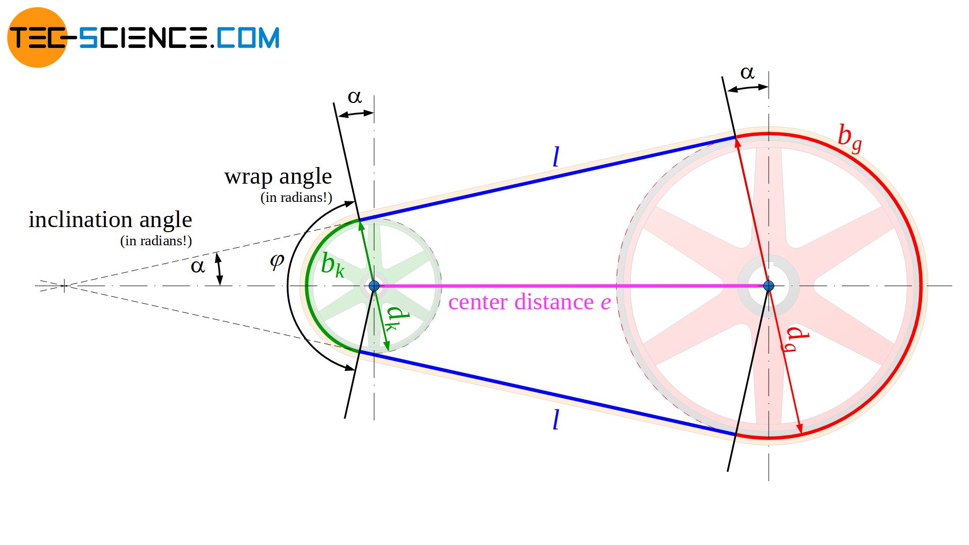
For belt drives, the principle for speed ratio is the same, but it uses pulley pitch diameters instead of tooth counts. The calculation for center distance is different because it depends on a flexible belt of a specific length.
Key Formulas:
-
Speed Ratio (i): Similar to gears, but using pulley pitch diameters ().
-
Belt Length (L) and Center Distance (C):
Unlike gears, belt systems involve a third component: the belt. In practice, you often work with standard, off-the-shelf belt lengths. The design process is typically:
a. Define pulley sizes and a target center distance.
b. Calculate the approximate belt length needed.
c. Select the closest standard belt length from a manufacturer's catalog.
d. Recalculate the actual center distance your mechanism must have to properly tension that standard belt.
This process is explained very well in the context of timing belts, which are common in custom machine design.
Timing Belt and Pulley Selection Calculation in Machine Design | Complete Guide
The following video gives a complete, practical guide to selecting a timing belt and pulley system. We will focus on the sections for sizing the pulleys and calculating the belt length.
Please watch the following two sections: Selection of pulley size (09:12 - 12:16): Pay attention to how the desired speed ratio (2:1 in his example) and other constraints (shaft size, available space) guide the selection of pulleys with a specific number of teeth. Calculation of the timing belt length (12:16 - 14:53): This is the key part. Notice the workflow: he uses the pulley sizes and a target center distance to calculate a theoretical belt length, then chooses the closest standard belt length from a catalog. This is exactly how it's done in a professional setting.
The formula for approximate belt length is:
Where:
- is the center distance.
- are the pulley pitch diameters.
Once a standard belt length is chosen, the center distance can be solved for, though often this is done within CAD or using online calculators from belt manufacturers, as the exact formula is more complex. The important takeaway is that the center distance in a belt drive is often adjustable to allow for tensioning.
Conclusion
In this lesson, we established the framework for selecting and sizing a power transmission system. You learned the critical trade-offs between gear and belt drives and are now able to perform the first-pass calculations that will define your powertrain's architecture.
Key Takeaways:
- Selection: Gear drives are suited for high-torque, compact, precision applications, while belt drives excel over long distances and in high-speed, low-noise, or cost-sensitive systems.
- Speed Ratio: For both systems, the speed ratio is the inverse of the ratio of the output and input diameters (or tooth counts for gears). .
- Center Distance (Gears): For gears, the center distance is fixed by the gear diameters: .
- Center Distance (Belts): For belts, the process is iterative. You calculate a theoretical belt length from a target center distance, choose a standard belt, and then determine the actual center distance your design must accommodate.
Preview of the Next Lesson:
Now that you have the fundamentals of speed ratios, our next lesson will go deeper into the world of gears. We will focus on the next step: Select gears and calculate gear ratios for power transmission. This will involve adding torque and power considerations to our calculations and exploring the different types of gears (spur, helical, bevel) in more detail.