Hello! Welcome back to our module on Design for Manufacturing and Assembly (DFMA).
In our last lesson, we focused on simplifying assemblies through part count reduction and component standardization. We established that the most effective way to improve an assembly is often to eliminate parts that aren't strictly necessary.
Today, we address the next logical step in the design process. Now that we've optimized what goes into the assembly, we need to ensure how it goes together is simple, efficient, and error-free. This lesson will focus on a key principle of Design for Assembly: making it physically obvious and easy for someone (or a robot) to assemble parts correctly, and impossible to assemble them incorrectly.
Your learning outcome for this session is to incorporate geometric features for error-proofing (poka-yoke) and to guide assembly orientation. As an engineer, mastering these techniques will not only reduce manufacturing costs by speeding up assembly but also improve product quality by preventing defects from ever occurring.
1. The Philosophy of Poka-Yoke: Mistake-Proofing by Design
Before we dive into specific geometric features, it's important to understand the guiding philosophy. This concept was developed in Japan and is known as Poka-Yoke (pronounced po-ka yo-kay), which literally translates to "mistake-proofing." The core idea is to shift from a mindset of inspecting for quality after the fact to designing for quality from the start.
To get a clear introduction to this powerful concept, please watch the beginning of the following video.
Poka Yoke (Error Proofing) - Meaning, Concept, Types, Stages, & Implementation Explained.
The video 'Poka Yoke (Error Proofing)' from Academic Gain Tutorials provides a concise explanation of the concept, its origins, and its importance in modern manufacturing.
Please watch from the beginning until 02:56. Pay close attention to the simple examples like the plug socket and the SIM card. These are perfect illustrations of how geometry can be used to prevent errors.
As the video highlights, Poka-Yoke isn't about adding complex inspection steps. It's about clever, often simple, design features that make incorrect actions impossible. Your experience with FMEA, which involves identifying potential failure modes, connects directly here. Poka-Yoke is a proactive way to design out the causes of assembly-related failure modes.
2. Guiding the Assembly: Self-Locating and Self-Fixturing Features
The first step toward error-proofing is to make assembly intuitive. We achieve this by designing parts to be self-locating. A self-locating feature guides a part into its correct position and orientation with minimal effort from the assembler. A related concept is self-fixturing, where parts are designed to hold themselves in place during subsequent operations like welding or fastening, reducing the need for expensive external jigs and fixtures.
The following article provides excellent, practical examples of how to achieve this for different manufacturing processes you're likely to encounter.
How to Design Assemblies to Be Self-Locating and Self-Fixturing
The article 'How to Design Assemblies to Be Self-Locating and Self-Fixturing' from Fictiv is full of industry-relevant techniques for mechanical designers.
Please read the sections titled 'Self-Locating in Sheet Metal Design', 'Self-Fixturing for Welding', and 'Self-Location Using Pins and Bosses'. As you read, think about how you could model these features in OnShape.
Let's summarize the key techniques from the article:
For Sheet Metal and Welded Parts: Tabs and Slots
This is a classic and highly effective technique. By adding a tab to one part that fits into a slot on the mating part, you precisely control the location in one or more directions. This removes ambiguity and reliance on measurement during assembly.
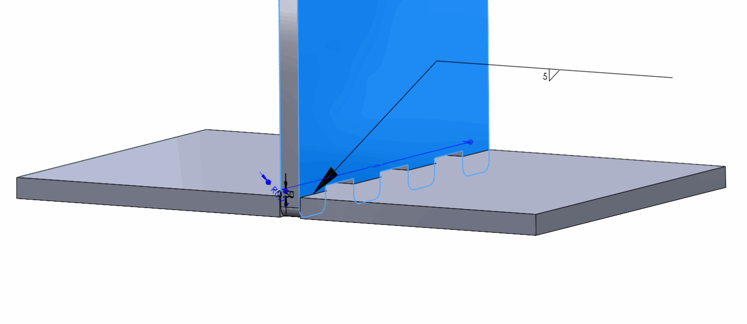
For Machined and Molded Parts: Pins, Bosses, and Chamfers
- Dowel Pins & Bosses: These cylindrical features are fundamental for alignment. A pin on one part fits into a hole (or a boss into a counterbore) on another, locking in the relative position. This is extremely common in everything from engine blocks to electronics enclosures.
- Chamfers and Tapers: These are crucial guiding features. Adding a generous chamfer to the entry of a hole or the end of a pin creates a "funnel" effect. This means the assembler doesn't need perfect initial alignment; the parts will guide themselves into place. This principle is explicitly mentioned in the textbook resource below.
Chapter 5 – Design for Manufacture and Assembly
The textbook chapter 'Design for Manufacture and Assembly' provides a structured list of principles for easy part insertion, reinforcing what we've just discussed.
Please read the section 'Ease of Part Insertion into the Assembly'. Focus on the bullet points under 'Part insertion considerations', such as 'Self-aligning parts', 'Self-locating parts', and 'One-way orientation'.
3. Achieving True Error-Proofing with Asymmetry
Self-locating features are great for making assembly easier, but to make it truly impossible to assemble incorrectly, we often need to introduce asymmetry.
Imagine you have a square lid that must fit onto a square box. If the lid is perfectly symmetrical, it can be installed in four different orientations. If one of those orientations is incorrect (e.g., it puts an internal electronic component in the wrong spot), you have a 75% chance of failure. By designing in asymmetry, you force a single, correct orientation.
This is the essence of Poka-Yoke in mechanical design.
How to Design Assemblies to Be Self-Locating and Self-Fixturing
Let's return to the Fictiv article, which has a specific section on this exact topic.
Please read the section titled 'Poka-Yoke – “Mistake-Proofing”'. It directly explains how to turn the self-locating features we just discussed into error-proofing features.
Here are the key methods for creating Poka-Yoke features:
- Asymmetric Patterns: Instead of a square pattern of four identical bolts, use a rectangular pattern, or a triangular pattern of three. An even simpler method is to use four bolts but offset one of them slightly. The part will now physically fit in only one orientation.
- Varying Feature Size/Shape: Use pins of different diameters or tabs of different widths. For example, if Part A needs to be attached to Part B, design it with one 8mm pin and one 5mm pin. The mating part must have corresponding 8mm and 5mm holes, making it impossible to install backward.
- Blocking Features: Add a small, seemingly non-functional rib or post whose only purpose is to physically interfere with the mating part if it's oriented incorrectly.
This image of a hard drive assembly shows these principles in a complex, real-world product.

A Critical Note on Tolerances: As the Fictiv article warns, be careful not to over-constrain your design. When adding locating features, ensure there is enough clearance to account for manufacturing variation. The goal is to make assembly easier, not to create a situation where perfectly good parts won't fit together because the tolerances are too tight. This is where your future work on tolerance stack-up analysis will be critical.
Test your understanding!
You are designing an enclosure for a small device. It consists of a rectangular base and a rectangular lid. The lid contains a small indicator LED that must be positioned over a sensor on the base. The base and lid are fastened with four screws, one at each corner.
How could you use geometric features in OnShape to ensure the lid is always installed in the correct orientation, preventing the LED from being misaligned? Describe two distinct methods.
Show answer
Here are two effective Poka-Yoke strategies:
-
Asymmetric Pin/Boss Feature: Add a small cylindrical boss to the underside of the lid, slightly offset from the center. Add a corresponding hole in the base. When the lid is placed on the base, it will only sit flush when the boss engages the hole, which can only happen in the single correct orientation. Attempting to install it 180 degrees rotated would cause the boss to hit the flat surface of the base, making the error immediately obvious.
-
Asymmetric Fastener Pattern: Instead of placing the four screw holes in a perfect rectangle, slightly shift the position of one of the holes (e.g., move the top-right hole 2mm further to the right). The corresponding tapped hole in the base must have the same offset. The lid will now only align with the screw holes in one orientation.
Both methods make incorrect assembly physically impossible or immediately apparent, which is the core goal of Poka-Yoke.
Conclusion
In this lesson, you've moved from simplifying an assembly's structure to refining its components for foolproof assembly. By incorporating deliberate geometric features, you can guide parts together and make incorrect assembly impossible.
Key Takeaways:
- Poka-Yoke is a design philosophy focused on preventing mistakes, not just catching them.
- Self-locating features like tabs, slots, pins, and bosses make assembly faster and more intuitive. Chamfers are crucial for guiding parts into position.
- Asymmetry is the key to turning a guiding feature into a true error-proofing feature. By breaking symmetry (e.g., with offset pins or varied feature sizes), you can enforce a single, correct assembly orientation.
- These techniques are not just theoretical; they are practical, low-cost methods used every day in professional engineering to improve quality and reduce cost.
Preview of the Next Lesson:
Now that we have a robust design that is simple and error-proof to assemble, a critical business and engineering question arises: which of these well-designed parts should we manufacture ourselves, and which should we buy from specialized suppliers? In our next lesson, you will learn how to justify make-versus-buy decisions using cost and capability analysis, an essential skill for any design engineer working in a commercial environment.