Hello! In our last lesson, we explored how the CPU actively communicates with peripheral devices using Memory-Mapped and Port-Mapped I/O. This covered one side of the conversation: the CPU talking to the hardware. But what about the other side? How does a device, like a keyboard or a timer, get the CPU's attention when it has something important to say?
This lesson answers that fundamental question. We will dive into the concept of hardware interrupts, the mechanism that allows peripheral devices to pause the CPU's current work and demand immediate service. Understanding this is not just a theoretical exercise; it is the absolute foundation for writing any device driver and making your operating system responsive to the outside world. By the end of this lesson, you will be able to explain exactly what a hardware interrupt is and trace the precise sequence of events the CPU follows when it receives one.
The Problem: Inefficiency of Polling
Imagine you're writing the code for your OS to read from the keyboard. How does your code know when a key has been pressed? One straightforward approach is polling. The CPU would have to run a loop that constantly asks the keyboard controller, "Do you have a new key press? ... How about now? ... Now?"
While simple, this is incredibly wasteful. The CPU, a highly complex and fast processor, would spend the vast majority of its time in a tight loop, repeatedly asking a much slower device for its status. Now, multiply this by every device in the system—the mouse, the hard disk, the network card. The CPU would be so busy polling that it would have little time left for running user programs or doing other useful work.
There has to be a better way. And there is.
How Interrupts Work in Modern Computers
This video from BitLemon provides an excellent introduction to the problem of polling and presents interrupts as the efficient alternative.
Watch the first two minutes, from the beginning to the end of the introduction of interrupts, explaining the problem. This will set the stage for why interrupts are so crucial in modern computing.
As the video explains, instead of the CPU asking the device, the device tells the CPU when it needs attention. This signal is called an interrupt.
The Interrupt Mechanism: A High-Level View
When a device triggers an interrupt, it sets in motion a chain of events that involves several key hardware components. The goal is to pause the currently running code, execute a special function to handle the device's request, and then seamlessly resume the original code as if nothing happened.
The diagram below shows the main players involved in this process. We will use this as our map for the rest of the lesson.
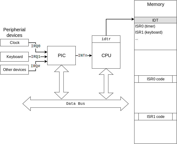
Let's break down each component's role:
- Peripheral Devices: These are the sources of interrupts, like the system timer, keyboard, or disk controller. Each is typically connected to a specific Interrupt Request (IRQ) line.
- Programmable Interrupt Controller (PIC): Since the CPU has a limited number of interrupt pins, it can't be connected to every single device. The PIC acts as a manager. It collects IRQ signals from multiple devices, prioritizes them, and forwards them to the CPU on a single interrupt pin. While modern systems use more advanced controllers (APICs), they often maintain backward compatibility with the classic PIC, which is what we'll focus on.
- CPU: The processor receives the interrupt signal from the PIC. It is then responsible for orchestrating the entire response.
- Interrupt Descriptor Table (IDT): This is a data structure in memory created and managed by the operating system. Think of it as an array where each index corresponds to a specific interrupt number. Each entry in the table contains the memory address of the function that should be executed to handle that interrupt. The CPU knows where to find this table because the OS loads its address into a special CPU register called the IDT Register (IDTR).
- Interrupt Service Routine (ISR): This is the actual code, written by the OS developer, that handles the interrupt. It's also called an "interrupt handler." There is a unique ISR for each type of interrupt (one for the keyboard, one for the timer, etc.). The IDT's job is to point the CPU to the correct ISR.
Now that we know the cast of characters, let's examine the main event: what exactly does the CPU do when that signal from the PIC arrives?
The CPU's Response: A Step-by-Step Breakdown
The CPU's response to an interrupt is a carefully choreographed sequence of hardware-level actions. It's designed to be fast, secure, and completely transparent to the interrupted program.
The "Impossible" Task of Saving State
When an interrupt occurs, the CPU is in the middle of executing some program. To handle the interrupt, it must jump to the ISR's code. But after the ISR is finished, we need to resume the original program precisely where it left off. This means we must save the CPU's exact state at the moment of the interrupt—most importantly, the value of the instruction pointer (EIP) and the status flags (EFLAGS).
This presents a fascinating chicken-and-egg problem. The very act of jumping to an interrupt handler involves changing the EIP register. If we need software to save the old EIP, how can it do so if the old EIP is already gone by the time the software starts running?
How Hardware Assist Software When Multitasking
This video from Core Dumped explores this exact problem in the context of multitasking, which relies on the same interrupt mechanism. It masterfully explains why saving the CPU's context cannot be done purely in software.
Watch the sections that introduce context switching, explain the impossibility of a software-only save, and finally reveal the hardware-assisted solution that x86 processors use.
As the video explains, this problem is solved by hardware. The CPU itself is designed to automatically perform the most critical parts of the state-saving procedure before executing the first instruction of the interrupt handler.
The Hardware-Assisted Interrupt Sequence
Here is the precise sequence of events that unfolds inside the CPU:
-
Interrupt Signal: A peripheral device asserts its IRQ line to the PIC. The PIC, in turn, asserts the interrupt pin on the CPU.
-
Instruction Completion: The CPU always finishes the instruction it is currently executing. This prevents the machine from being left in an inconsistent state.
-
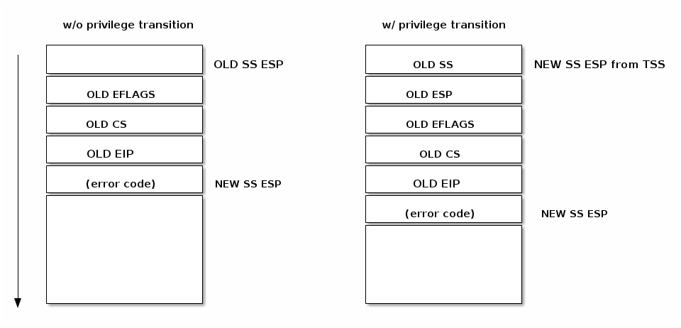
State Save (Hardware Magic): This is the crucial step. Before doing anything else, the CPU hardware automatically pushes several critical registers onto the current stack. In 32-bit protected mode, this includes:
- The
EFLAGSregister (containing status flags like the carry flag, zero flag, etc.). - The
CS(Code Segment) register. - The
EIP(Instruction Pointer) register, which holds the address of the next instruction to be executed in the interrupted program.
If the interrupt causes a change in privilege level (e.g., from user mode to kernel mode), the hardware also pushes the old stack pointer (
ESP) and stack segment (SS). This is to ensure the kernel uses its own secure stack, not the potentially corrupt stack of a user program. - The
-
Acknowledge and Identify: The CPU sends an acknowledgment signal back to the PIC. The PIC then places the unique interrupt vector number (from 0 to 255) on the data bus for the CPU to read. For example, by default, the keyboard (IRQ1) corresponds to interrupt vector 9.
-
Find the Handler: The CPU uses this vector number as an index into the Interrupt Descriptor Table (IDT). It locates the IDT in memory using the address stored in its
IDTRregister. -
Jump to the Handler: The CPU reads the appropriate entry from the IDT, which contains the segment selector and offset for the ISR. It loads these values into the
CSandEIPregisters. The CPU is now executing the first instruction of your interrupt handler. As part of this, the hardware may also clear the Interrupt Flag (IF) in theEFLAGSregister, which temporarily disables further hardware interrupts. This prevents a new interrupt from disrupting the handling of the current one.
This entire sequence, from step 2 to 6, happens automatically in hardware. By the time your OS code starts running, the essential state of the interrupted program is already safely stored on the stack.
The following text provides a more detailed look at the process, including the structure of the IDT and the responsibilities of the ISR.
Basic x86 interrupts | There is no magic here
This article from alex.dzyoba.com gives a great, practical overview aimed at hobby OS developers. It neatly summarizes the roles of the IDT and ISRs.
First, read the section on the Interrupt Descriptor Table to understand its structure. Then, read the section on Interrupt Service Routines, paying close attention to the list of actions the CPU performs "behind the curtain" when an interrupt occurs.
The Handler's Role and The Graceful Exit
Once the CPU jumps to the ISR, the OS is in control. The ISR's job is to:
- Save the rest of the context: The hardware only saves the most critical registers. The ISR must save any other general-purpose registers it plans to use (e.g.,
EAX,EBX) by pushing them onto the stack. - Service the device: This is the main work. For a keyboard interrupt, this means reading the key scan code from the keyboard controller's I/O port. For a timer interrupt, it might mean incrementing a system-wide tick counter.
- Acknowledge the PIC: The ISR must send an "End of Interrupt" (EOI) command back to the PIC. This tells the PIC that it's ready to accept new interrupts.
- Restore context and return: The ISR pops the general-purpose registers it saved. Finally, it executes a special instruction:
IRET(Interrupt Return).
The IRET instruction is the counterpart to the hardware's automatic state save. It pops the EIP, CS, and EFLAGS (and ESP/SS if applicable) from the stack and loads them back into the CPU's registers. The original program resumes execution exactly where it left off, completely unaware that it was ever paused.
To see how all these pieces fit together, let's trace a keyboard press from start to finish.
Basic x86 interrupts | There is no magic here
We will continue with the same article.
Read the final section, "Putting it all together", which walks through the complete lifecycle of a keyboard interrupt. This provides a perfect concrete example of the theory we've just discussed.
Conclusion
In this lesson, we have peeled back the layers of one of the most fundamental mechanisms in a modern computer. You now have a solid conceptual grasp of how external hardware can command the CPU's attention.
- Key Takeaways:
- Interrupts are signals from devices that are far more efficient than polling.
- The interrupt handling mechanism involves a partnership between hardware (Device, PIC, CPU) and software (OS-provided IDT and ISRs).
- The CPU's response is largely automated by hardware. It automatically saves the critical execution state (EIP, CS, EFLAGS) to the stack before jumping to the ISR.
- The IDT acts as a crucial dispatch table, mapping interrupt numbers to the correct handler code.
- The special
IRETinstruction is used to cleanly restore the saved state and resume the interrupted program.
We've covered the theory behind what an interrupt is and how the CPU responds. In our next module, we will put this theory into practice. Our very first step will be to move from theory to implementation by designing, creating, and loading our kernel's own Interrupt Descriptor Table.