Hello! In our previous lesson, we investigated the memory hierarchy, a crucial architectural design that bridges the speed gap between the CPU and main memory. We saw how caching and the principle of locality create the illusion of a large, fast memory. You now understand how the CPU communicates efficiently with memory.
This lesson shifts our focus from memory to the rest of the universe, from the CPU's perspective. How does the processor communicate with the vast array of peripheral devices attached to a computer—keyboards, disk drives, network cards, and timers? We will explore the two fundamental strategies for hardware communication: Memory-Mapped I/O (MMIO) and Port-Mapped I/O (PMIO). Understanding this distinction is not just an academic exercise; it is the prerequisite for writing the device drivers that will bring your operating system to life.
The Problem: CPU and the Outside World
A CPU is a master of computation, but it's not designed to manage the low-level mechanics of every peripheral. Forcing a multi-gigahertz processor to manually scan keyboard switches or position the read/write head of a disk drive would be an immense waste of its power.
To solve this, hardware devices are managed by their own specialized processors or logic circuits, known as device controllers. The CPU communicates with the controller, not the device itself, by sending high-level commands (e.g., "read this block from the disk") and receiving data back. This begs the question: how does the CPU talk to these controllers?
The following video provides an excellent overview of this relationship and why offloading this work to controllers is so important.
How CPUs Interact with So Many Different Devices
This video from the channel Core Dumped explains the fundamental concept of device controllers and sets the stage for I/O communication strategies.
Please watch the segment from the introduction to the end of the "first lesson learned" summary, communicating with devices. Pay close attention to the keyboard and hard drive examples, which illustrate why direct CPU management of devices is inefficient.
As the video explains, the CPU communicates with controllers rather than controlling devices directly. This communication needs a clear, defined method. Architects have converged on two primary approaches, which you can think of as two different philosophies for organizing the "phone book" the CPU uses to contact these controllers.
Two Philosophies: Memory-Mapped vs. Port-Mapped
The central design choice is this: should device controllers be addressed in the same way as memory, or should they have a completely separate addressing system?
-
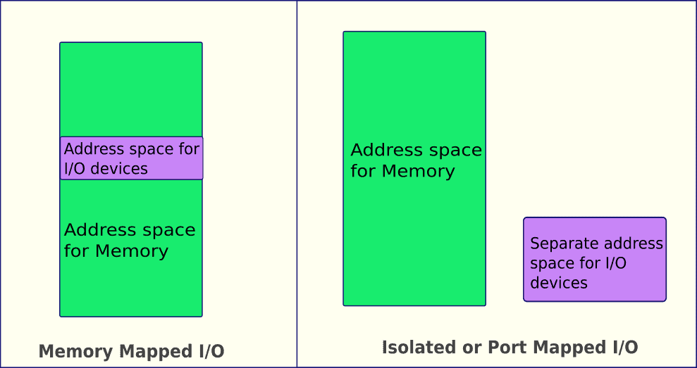
Memory-Mapped I/O (MMIO): In this model, the control registers and data buffers of a device controller are mapped into the physical memory address space. The CPU uses the same instructions to talk to a device as it does to read from or write to RAM.
-
Port-Mapped I/O (PMIO): Also known as Isolated I/O, this model gives devices a completely separate address space, called the "I/O port space." The CPU must use special, dedicated instructions to communicate with devices through this separate channel.
The image below visually contrasts these two philosophies.
Let's dive into the details of each approach.
Memory-Mapped I/O (MMIO)
In an MMIO system, there is no conceptual difference between accessing memory and accessing a device. If a device's control register is mapped to physical address 0xFEE00000, the CPU writes to that register by executing a standard move instruction to that address.
From a C programmer's point of view, this is beautifully simple. You can define a pointer to the device's register and interact with it just like any other variable in memory:
// Example of writing to a memory-mapped register
// 'volatile' is crucial here to prevent compiler optimizations
volatile unsigned int* device_register = (unsigned int*)0xFEE00000;

// Send a command to the device by writing a value
*device_register = 0x1;
Advantages of MMIO:
- Simplicity: The CPU doesn't need special I/O instructions. This aligns with RISC (Reduced Instruction Set Computer) design principles and can lead to simpler CPU hardware.
- Flexibility: Any instruction that can operate on memory can be used on device registers. You can add, compare, or perform bitwise operations directly on the device's registers without loading them into a CPU register first.
Disadvantage of MMIO:
- Address Space Consumption: Every memory-mapped device consumes a portion of the physical address space, making it unavailable for use by actual RAM.
The following document explains this in more detail.
These lecture slides offer a concise, technical breakdown of I/O on x86 systems.
Read the two slides titled "Memory-Mapped I/O" (page 4-6). Focus on the key takeaway: when the CPU accesses a memory-mapped address, the hardware routes the request to the device, not to RAM.
Port-Mapped I/O (PMIO)
In a PMIO system, the CPU uses a separate address bus or a special signal pin to indicate that it wants to talk to an I/O port, not a memory location. On x86 processors, this is handled by the IN and OUT assembly instructions.
For example, to send the byte 0x42 to I/O port 0x60, the assembly code would be:
mov al, 0x42  ; Move the value into the AL register
out 0x60, al  ; Output the value in AL to port 0x60
Notice that this requires a specific instruction (out) designed solely for I/O.
Advantages of PMIO:
- No Memory Address Consumption: The full physical address space remains available for RAM.
- Clear Separation: It's immediately obvious from the instruction used that the code is performing an I/O operation, which can sometimes make low-level code easier to read.
Disadvantages of PMIO:
- CPU Complexity: The CPU must implement special instructions and logic to handle a separate I/O address space. This is characteristic of CISC (Complex Instruction Set Computer) designs like x86.
- Limited Instructions: The operations you can perform are restricted to what the special I/O instructions allow, which is typically just loading from and storing to a port. More complex operations require reading the value into a CPU register first, modifying it, and then writing it back.
The reading below provides the specifics for x86.
We'll continue with the same lecture slides.
First, read the two slides titled "Port I/O Address Space" and "Port I/O Accesses" (pages 8-9). Note the size of the I/O space on x86 (64 KB). Then, jump to the slides that detail the IN and OUT instructions (pages 18-22). Don't worry about memorizing the assembly syntax; focus on the concept that these are special instructions for I/O.
How Does the Hardware Know?
Given your background in electronics, you might be wondering how this is implemented at the hardware level. How does the system differentiate between a memory access and an I/O access?

As shown in the diagram, the chipset contains logic (the Address Code Decoder) that constantly monitors the address bus.
- For an MMIO access, the decoder is programmed to recognize certain address ranges as belonging to devices. If it sees an address in the range
0xF0000000 - 0xFFFFFFFF, for example, it might activate a PCI Express device instead of the RAM controller. - For a PMIO access, the CPU asserts a special signal (like the
M/IO#pin on older processors) along with the port address. The decoder sees this signal and knows to route the request to the I/O controller hub, which manages the port space, completely bypassing the memory controller.
x86: A Hybrid Approach
Different CPU architectures make different choices. ARM, common in mobile devices, is a RISC architecture and uses MMIO exclusively. The x86 architecture, which our OS will target, is a CISC architecture and supports both PMIO and MMIO.
In the x86 world, you will encounter both:
- PMIO is used for many legacy devices that have been part of the PC standard for decades. This includes the keyboard controller (ports
0x60and0x64), the Programmable Interval Timer (PIT), and the Real-Time Clock (RTC). A common pattern for these devices is the index/data pair, where you write an index/offset to one port to select a register, and then read/write the data for that register from a second port. - MMIO is used for modern, high-performance devices where large, fast data transfers are critical. The most prominent example is the video card's framebuffer, where the screen's pixel data is stored. To draw to the screen, the OS simply writes pixel values into a specific region of memory. Other examples include the APIC (Advanced Programmable Interrupt Controller) and PCI Express configuration space.
As an OS developer, you'll need to be comfortable with both. When we write our keyboard driver, we will use IN and OUT instructions (wrapped in C functions) to talk to I/O ports. When we write our console driver to print text to the screen, we will write directly to a memory-mapped video buffer.
The following short video provides a great animated summary of everything we've discussed.
Memory Mapped IO vs Port Mapped IO (Animation)
This animation from BitLemon provides a quick, visual recap of the differences between port-mapped and memory-mapped I/O.
Please watch the entire video from the introduction. It's a great way to solidify your understanding of the concepts.
Conclusion
In this lesson, we have demystified how a CPU communicates with the outside world. You now understand the two primary strategies for this communication and their respective trade-offs.
- Key Takeaways:
- CPUs offload the management of peripheral devices to specialized device controllers.
- Memory-Mapped I/O (MMIO) integrates device registers into the main memory address space, allowing the use of standard memory access instructions. It is simple and flexible but consumes memory address space.
- Port-Mapped I/O (PMIO) uses a separate, isolated I/O address space, requiring special CPU instructions (
IN/OUTon x86). It preserves the memory address space but adds complexity to the CPU. - The x86 architecture, which we will be using, employs a hybrid approach, using PMIO for legacy devices and MMIO for modern, high-performance hardware.
We have now covered how the CPU initiates communication with devices. But communication is a two-way street. How does a device get the CPU's attention when it has data ready or has completed a task? In our next lesson, we will answer this by exploring hardware interrupts, the mechanism that allows devices to interrupt the CPU and demand service.