Hello! Welcome to your next lesson on UK electrical grids.
In our last session, we identified the 14 Distribution Network Operators (DNOs) and the regions they serve. We now know who is responsible for the local power lines that bring electricity to our homes and businesses.
Today, we'll explore how these DNOs ensure the network remains safe and reliable. Power grids are complex, and things can go wrong. This lesson focuses on what happens when they do. The learning outcome is to define common electrical faults (e.g., short circuits) and explain the fundamental principles of network protection (detection, isolation, coordination).
We will cover:
- What an electrical fault is and how it differs from an overload.
- The most common types of faults you'll find on the network.
- The fundamental principles used to protect the grid from the damage these faults can cause.
1. What is an Electrical Fault?
At the most basic level, an electrical fault is any condition that causes electric current to flow through an unintended path. This is different from an overload, where too much current flows through the intended path (for example, plugging too many appliances into one socket).
The key difference is the pathway of the current.
- Overload: Too much current in the correct path. This causes gradual overheating.
- Fault: Current flowing in an incorrect path, often with very little resistance. This causes a sudden, massive, and dangerous surge of current.
To understand this crucial distinction, let's watch a short video.
Overcurrent, Overload, Short Circuit, and Ground Fault
This video from Dave Gordon provides a very clear explanation of the difference between an overload and a fault, such as a short circuit.
Please watch from 01:22 to 06:51. Focus on these key points: The description of an overload as current flowing in the 'proper pathway' (01:22). The definition of a short circuit as current taking a 'shortcut' or 'wrong pathway' (03:17). The summary of the main differences in terms of pathway, current magnitude, and how quickly a protective device must react (05:21).
As the video explained, faults like short circuits are far more dangerous than overloads because the current can be thousands of times higher than normal, capable of causing near-instantaneous damage, fire, or electric shock.
2. Common Types of Electrical Faults
Now that we have a general definition, let's categorise the main types of faults. This flowchart gives a good overview of how faults are classified.
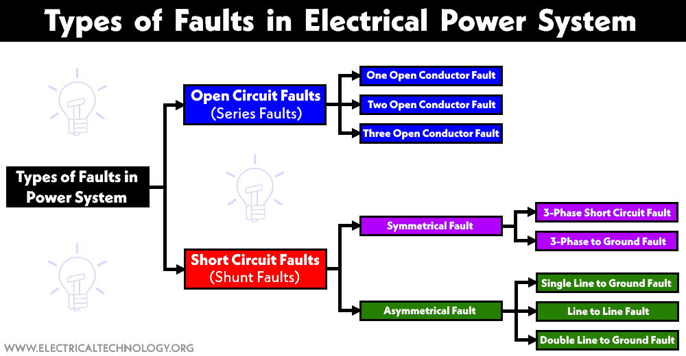
The most common and disruptive faults on the network are short circuits. Let's look at the main types.

To build on these visuals, let's read a brief description of these fault types and their classifications.
What Is An Electrical Fault – Types, Causes, Protection
This article from the Electricity Forum provides clear definitions and classifications for different electrical faults.
Please read the sections 'Classifications of Electrical Faults' and 'Types of Electrical Faults in Power Systems'. Focus on understanding the meaning of: Transient vs. Permanent faults. Symmetric vs. Asymmetric faults. The descriptions of line-to-ground, phase, and short circuit faults.
To summarise, the most important faults to be aware of are:
- Line-to-Ground Fault: A single energised conductor makes contact with the ground (e.g., a power line falls onto the earth). This is the most common type of fault on the grid.
- Line-to-Line Fault: Two energised conductors make contact with each other (e.g., strong winds cause two power lines to touch).
- Three-Phase Fault: All three conductors of a three-phase line are short-circuited together. This is a "symmetric" fault and, while rare, it is typically the most severe, resulting in the largest fault currents.
3. The Fundamental Principles of Network Protection
Since faults are inevitable, DNOs must have systems in place to manage them safely. This is called network protection. The goal is not to prevent every fault, but to minimise its impact when it occurs.
The entire process can be broken down into three core principles: Detection, Isolation, and Coordination.
A. Detection and Isolation
First, the system must be able to detect that a fault has occurred. Then, it must isolate the faulty section of the network from the rest of the healthy system.
This article from Roadnight Taylor, a UK-based power consultancy, clearly defines the two primary activities of network protection.
Please read the section 'What is network protection?'. Note how it frames the process in two steps: detection and disconnection (isolation).
- Detection: This is done by protective devices called relays. Relays are the "brains" of the system. They constantly monitor the electrical conditions (like current and voltage) on the network. When they measure values outside the normal operating range, they identify a fault.
- Isolation: Once a relay detects a fault, it sends a trip signal to a circuit breaker. A circuit breaker is a heavy-duty switch that can safely interrupt the massive current flowing during a fault. By opening, it disconnects the faulty line or equipment, thereby isolating the problem.
Common protective devices include:
- Fuses: Simple, single-use devices that melt to break a circuit during an overcurrent. Used in lower-voltage parts of the network and in homes.
- Circuit Breakers and Relays: Re-usable, sophisticated systems used throughout the high-voltage transmission and distribution grids.
B. Coordination
Simply detecting and isolating faults isn't enough. A large, interconnected network has many circuit breakers. If a fault occurs on a small local street, you don't want the circuit breaker for the entire town to trip.
Coordination (or 'selectivity') is the principle of ensuring that only the circuit breaker closest to the fault operates, leaving the rest of the network powered on. This is crucial for maintaining reliability.
One way to achieve coordination is by programming relays to operate at different speeds depending on the fault's severity and location. This relationship is often visualised on a Time-Current Curve.
Electrical faults explained: types, causes, calculations, and protection | Eaton PSEC
This video from Eaton explains the concept of a Time-Current Curve, which is fundamental to understanding protection coordination.
Please watch from 04:45 to 06:00. Focus on the explanation of the Time-Current Curve. Notice how the device will trip very quickly for high currents (like a short circuit) but will wait longer for lower currents (like a small overload).
By setting the time-current curves of different relays in a sequence, engineers ensure that the relay nearest the fault trips first. If it fails for some reason, the next one upstream will operate after a short delay, acting as a backup. This tiered approach, from fast local protection to slower backup protection, is the essence of coordination.
On more advanced parts of the grid, other protection schemes are used to achieve even better coordination:
- Distance Protection: The relay calculates the distance to the fault by measuring voltage and current. It can then decide whether the fault is in its primary zone of protection and trip instantly, or in a backup zone and trip with a delay.
- Differential Protection: This scheme works on the principle that "what goes in must come out." It measures current at both ends of a piece of equipment (like a transformer or a cable). If the currents don't match, it means current is leaking out through a fault, and the relay trips the breakers at both ends to isolate it.
Conclusion
In this lesson, we've moved from the physical assets of the distribution network to the principles that keep it operating safely.
Here are the key takeaways:
- An electrical fault is an abnormal condition where current flows through an unintended path, which is distinct from an overload.
- Common faults include line-to-ground and line-to-line short circuits, which can cause massive and dangerous current flows.
- Network protection is based on three fundamental principles:
- Detection: Identifying a fault by monitoring current and voltage (using relays).
- Isolation: Disconnecting the faulty section to prevent damage and protect the rest of the system (using circuit breakers).
- Coordination: Ensuring that only the protective device closest to the fault operates, maximising supply reliability.
In our next lesson, we'll begin to look at the challenges that modern energy systems introduce. We will explain how distributed generation (like solar panels) can cause reverse power flow and voltage rise issues in radial distribution networks, problems that require new ways of thinking about network operation and protection.