Welcome back. In our previous lesson, we examined the CHIP-8's graphical output system, focusing on its 64x32 monochrome display and the unique XOR-based logic for drawing sprites. This gave us insight into how a CHIP-8 program visualizes its state. Now, we turn our attention from output to input, exploring how the user interacts with the virtual machine.
This lesson addresses the CHIP-8's input mechanism: the 16-key hexadecimal keypad. We will describe its physical layout, how it's adapted for modern keyboards, and its function within the CHIP-8 instruction set. Understanding the keypad is the penultimate step in our architectural survey. Once we cover this and the timers in the next lesson, we will have a complete model of the CHIP-8 system, preparing us to shift our focus toward implementation in JavaScript.
The 16-Key Hexadecimal Keypad
Unlike modern computers with full QWERTY keyboards, the original hardware that ran CHIP-8, such as the COSMAC VIP, used a simple 16-key keypad. Each key corresponds to a single hexadecimal digit: 0 through F.
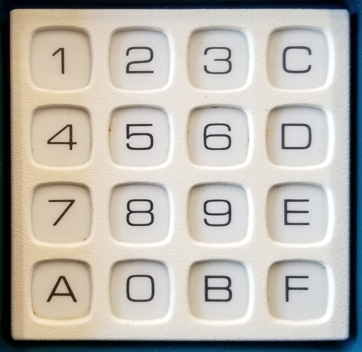
While several physical layouts existed, the one used by the COSMAC VIP has become the de facto standard for emulators. This layout arranges the 16 keys in a specific 4x4 grid.
For emulators running on modern PCs, these 16 virtual keys must be mapped to physical keys. By convention, a 4x4 block on the left side of a QWERTY keyboard is used.

The following reading describes both the original hexadecimal layout and its conventional mapping to a modern keyboard.
Guide to making a CHIP-8 emulator - Tvil
This section from Tobias V. Langhoff's guide provides the essential details on the keypad's layout and its modern adaptation.
Please read the section under the heading Keypad. Pay attention to the two tables: the first shows the standard 4x4 hexadecimal keypad layout, and the second shows how it is typically mapped to a QWERTY keyboard.
Modes of Input: Polling vs. Blocking
A CHIP-8 program can interact with the keypad in two fundamentally different ways, a distinction that should be familiar from your work in systems programming and embedded devices. These methods can be described as polling ("immediate mode") and blocking ("wait mode").
The following video provides a concise explanation of these two approaches.
This segment from VoxelRifts' "Making a Chip-8 Emulator" clearly distinguishes between the two ways CHIP-8 handles key input.
Watch from this section where the presenter describes the keypad and the two input methods: "immediate mode" and "wait mode." This will frame our discussion of the specific opcodes.
As the video explains:
- Polling (Immediate Mode): The program checks the current state of a specific key (is it pressed right now?) and continues execution. This is useful for real-time control, like moving a character in a game.
- Blocking (Wait Mode): The program halts execution and waits until a key is pressed. This is used when the program requires user input to proceed, such as at a menu screen.
CHIP-8 provides distinct instructions for each of these input models.
Keypad Instructions
The function of the keypad is realized through three main opcodes. Two are for polling, and one is for blocking.
Polling Instructions: EX9E and EXA1
These instructions are conditional skips. They check the state of the key specified in register VX and, based on the result, either skip the next instruction or continue normally.
EX9E- SKP Vx (Skip if Key Pressed): If the key corresponding to the value inVXis currently held down, the program counter is incremented by an extra 2 bytes, effectively skipping the next instruction.EXA1- SKNP Vx (Skip if Key Not Pressed): Conversely, if the key corresponding to the value inVXis not currently held down, the program counter is incremented to skip the next instruction.
These instructions allow for simple input-driven logic, such as a loop that continues as long as a key is not pressed.
Blocking Instruction: FX0A
This instruction is fundamentally different. It halts the normal execution flow of the emulator.
FX0A- LD Vx, K (Load Key Press into Vx): The emulator stops fetching and executing instructions until a key is pressed. Once a key is pressed, its hexadecimal value (0throughF) is stored in registerVX, and execution resumes.
This is a powerful but tricky instruction. As we'll see during implementation, handling this "blocking" behavior in a modern, event-driven environment like a web browser requires careful design to avoid freezing the entire application. The original COSMAC VIP even waited for the key to be released before registering the press, a nuance some emulators replicate for authenticity.
The following reading from the same guide provides more detail on these three instructions.
Guide to making a CHIP-8 emulator - Tvil
This reading covers the specific opcodes that handle keyboard input.
First, read the subsection Skip if key. Then, find the later subsection titled Get key and read its first two paragraphs. This will solidify your understanding of how polling and blocking are implemented at the instruction level.
Conclusion
In this lesson, we have demystified the CHIP-8's user input system. From its hardware origins to its modern software implementation, the keypad is a simple yet effective mechanism for user interaction.
The key takeaways are:
- The CHIP-8 was designed for a 16-key hexadecimal keypad (
0-F). - A standard 4x4 layout from the COSMAC VIP is commonly used in emulators, with a conventional mapping to the QWERTY keyboard.
- Input is handled through two primary methods:
- Polling: Using
EX9EandEXA1to check the current state of a key without halting execution. - Blocking: Using
FX0Ato pause the program until a key is pressed and then storing its value.
- Polling: Using
We have now covered the memory, registers, instruction format, display, and keypad. Only one architectural component remains. In our next lesson, we will explore the delay and sound timers, which provide a basic sense of timing and audio feedback. With that, our theoretical model of the CHIP-8 virtual machine will be complete.