Welcome back. In our last session, we demystified the CHIP-8 instruction format, learning how every command is a 2-byte opcode packed with information. We saw how bitwise operations are used to decode these opcodes and extract fields like register identifiers and immediate values. This process is the "decode" part of the CPU's fetch-decode-execute cycle.
This lesson moves from processing instructions to producing output. We will examine the CHIP-8's graphical output system: its display. This is a crucial component, as it's the primary way the user sees the results of the running program. Our goal is to describe the display's specifications, including its simple resolution and, most importantly, the clever XOR-based logic it uses for drawing. This will be the final major piece of the system's architecture we study before moving on to the keypad and timers.
The CHIP-8 Screen: A Minimalist Canvas
The CHIP-8 was designed for simple hardware, and its display reflects this. The specification calls for a monochrome display with a resolution of 64x32 pixels. By modern standards, this is incredibly small, but it was sufficient for the simple games and applications of its era.

"Monochrome" means each pixel has only two states: on or off. We can represent this state with a single bit (1 for on, 0 for off). The entire 64x32 grid of pixels, known as the framebuffer, can therefore be stored in 64 * 32 = 2048 bits, which is exactly 256 bytes of RAM. Your emulator will need to reserve a 256-byte array to represent this display memory.
The following reading provides a concise overview of these characteristics.
Guide to making a CHIP-8 emulator - Tvil
This section of Tobias V. Langhoff's guide succinctly describes the display's core properties.
Please read the first three paragraphs under the heading Display. Focus on the resolution, the monochrome nature of the pixels, and the introduction to how sprites are drawn.
Drawing with Sprites and XOR
The CHIP-8 doesn't have commands to draw individual pixels, lines, or shapes. Instead, all drawing is done by rendering small bitmap images called sprites. In CHIP-8, a sprite is always 8 pixels wide and can be 1 to 15 pixels tall. We've already seen examples of sprites when we looked at the built-in font set; each character like 'A' or 'F' is a 5-byte (8x5 pixel) sprite.
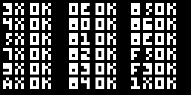
The core drawing operation is the DXYN instruction. It instructs the CPU to draw a sprite of height N at the screen coordinates stored in registers VX and VY. The sprite's pixel data is read from memory, starting at the address stored in the I register.
The most interesting part of this process is how the sprite is drawn. Instead of simply overwriting the pixels on the screen, CHIP-8 uses a bitwise XOR operation. The bits of the sprite are XORed with the bits already on the screen at the target location.
This has a few important consequences:
0 (screen) XOR 1 (sprite) = 1: A pixel is turned on.1 (screen) XOR 1 (sprite) = 0: A pixel is turned off.1 (screen) XOR 0 (sprite) = 1: A pixel remains on. (Sprite bits of 0 are transparent).
This means drawing the same sprite at the same location twice will erase it, restoring the background perfectly. This was a common and efficient technique for animation on early systems.
The following video segment demonstrates this XOR logic being implemented in JavaScript for an emulator's setPixel function.
Building and understanding a Virtual Machine in 2hrs (CHIP-8 Emulator)
This clip from "Building and understanding a Virtual Machine in 2hrs" shows the practical implementation of the display buffer and the XOR drawing logic.
Watch from this section where the presenter implements the setPixel function. Pay close attention to how he uses the XOR operator (^) to toggle the pixel's state in the display array and returns whether the pixel was turned off.
Collision Detection via Drawing
The XOR drawing mechanism provides a clever, built-in method for collision detection. The CHIP-8 specification states that the VF register (often used as a special-purpose flag) must be set to 1 if any screen pixel is flipped from on to off during a draw operation. Otherwise, VF is set to 0.
This happens only in the 1 XOR 1 = 0 case. In game development terms, this means if a sprite is drawn on top of an existing "on" pixel (part of another sprite), a "collision" is detected. This allows games to detect, for example, when a player's ship hits an enemy, or a ball hits a paddle.
Your background in hardware design will give you an appreciation for how this can be implemented at the logic gate level. The following resource discusses building a CHIP-8 on an FPGA and explains collision detection from a hardware perspective.
CHIP-8 in hardware - part 3 (drawing, VGA) | Juraj's Blog
This blog post by Juraj Borza provides a hardware-centric view of sprite drawing, which aligns well with low-level system design principles.
Read the short subsection titled Collisions. The author explains how to detect a collision in Verilog. The logic |(mem_read_data & sprite_row[15:8]) is a compact way to check if any bits are set in both the existing screen data (mem_read_data) and the incoming sprite data. If any corresponding bits are 1, their AND will be 1, and the unary OR (|) over the result will yield a 1, flagging a collision.
This hardware implementation detail is the logical equivalent of checking if (screen_pixel == 1 && sprite_pixel == 1) before performing the XOR.
The Full DXYN Algorithm
We can now assemble these concepts into the complete algorithm for handling the DXYN instruction. It involves fetching coordinates, looping through sprite data, performing the XOR draw, and handling collision detection and screen boundaries. The resource from our previous lesson, Tobias V. Langhoff's guide, contains an excellent, detailed breakdown of this process.
Guide to making a CHIP-8 emulator - Tvil
This section details the most complex instruction in the CHIP-8 set, DXYN.
Please read the entire section for the DXYN instruction. It provides a comprehensive step-by-step summary that covers: Fetching coordinates from registers VX and VY. Wrapping the starting coordinates if they are off-screen. Clipping (not wrapping) the sprite if it draws past an edge. The nested loop structure for iterating over sprite rows and pixels. The logic for flipping pixels and setting the VF collision flag.
Conclusion
In this lesson, we have explored the final major component of the CHIP-8's core architecture: its display system. We have a complete picture of how the virtual machine visualizes its state for the user.
The key takeaways are:
- The display is a 64x32 monochrome grid, with its state stored in a 256-byte framebuffer in RAM.
- All drawing is performed with the
DXYNinstruction, which renders 8-pixel-wide sprites. - Pixels are not set but are flipped using a bitwise XOR operation, which allows for simple animation by drawing a sprite twice to erase it.
- The
VFregister is used for collision detection, flagging when a sprite pixel is drawn over an existing screen pixel, causing it to be erased.
With our understanding of the memory map, registers, instruction format, and now the display, our architectural blueprint of the CHIP-8 is nearly complete. In the next lesson, we will cover the last two pieces of the puzzle: the 16-key keypad for user input and the two system timers. After that, you will be fully equipped to begin the implementation.