Hello! Welcome back.
In our last lesson, we created the physical layout for our villa project, carefully placing MP Rotators for the lawn and a mix of dripline and point-source emitters for the planting beds and trees. We now have a complete map of where every component goes.
Today, we'll organize this layout into a functional system. The goal of this lesson is to group all emitters into logical hydraulic zones based on flow rate and component type. Just as an architect divides a building's electrical plan into circuits, we must divide our irrigation plan into hydraulic zones. Each zone is a group of sprinklers or drippers that will be turned on and off together by a single valve. This is the crucial step that translates your spatial design into a workable hydraulic schematic.
1. What is an Irrigation Zone?
At its simplest, an irrigation zone (also called a "station") is a set of emitters controlled by a single automatic valve. Your irrigation controller sends an electrical signal to the valve, which opens and allows water to flow only to the emitters in that specific zone. The system then cycles through the zones one by one.

To understand the terminology, let's refer to a standard glossary.
The 'Basic Irrigation Design' workbook by Toro provides clear definitions for the key terms we'll be using.
Please review the 'Terminology' section on pages ii and iii. Pay special attention to the definitions of Zone, Station, Remote Control Valve, Main Line, and Lateral.
2. The Three Fundamental Rules of Zoning
Grouping emitters into zones isn't arbitrary. It follows three strict rules designed to ensure the system is efficient, effective, and doesn't overwhelm your water source.
Rule #1: Respect the Available Flow Rate
This is the most critical hydraulic constraint. Your water source (whether from a city connection or a pump) can only supply a certain amount of water at a given pressure. This is your system design capacity, which we determined in an earlier module.
The total flow rate of all emitters in a single zone must never exceed the system's design capacity.
If a zone's demand is higher than the supply, the pressure will drop dramatically, and sprinklers will fail to pop up or achieve their intended radius, resulting in poor coverage and dry spots.
The Hunter 'Irrigation System Design' guide explains this principle clearly in its section on circuiting sprinklers.
Read the section titled 'Circuiting Sprinklers Into Zones'. Focus on the formula provided for calculating the number of zones based on the total flow and the design capacity. Notice the advice to balance the flow requirements between zones.
Rule #2: Group Like Components Only
This is a "golden rule" of irrigation design. Because different types of emitters apply water at vastly different rates (known as precipitation rates), they must be on separate zones.
- Never mix sprinkler types: Do not put spray heads, rotors, or MP Rotators on the same zone. Sprays might apply water at 40 mm/hr, while rotors apply it at 10-15 mm/hr. If you ran them together for the same amount of time, the spray area would be flooded while the rotor area would be bone dry.
- Never mix sprinklers and drip irrigation: This is an absolute rule. Sprinklers require high pressure (2.5-4 bar) and high flow, while drip systems require low pressure (1-1.5 bar) and low flow. They are fundamentally incompatible on the same valve.
Rule #3: Align with Hydrozones
This rule connects our hydraulic design back to the horticultural needs of the landscape. A single hydraulic zone should, whenever possible, water only one type of hydrozone.
To review the logic behind this, let's revisit the Toro design workbook.
The 'Zoning a System' section of the Toro guide outlines several other key considerations for grouping sprinklers, which directly relate to the hydrozones we established.
Read the list under 'Some of the other considerations for zoning include:'. This list summarizes why we separate zones for: Different plant materials (e.g., lawn vs. shrubs) Different sun exposures (sunny vs. shaded areas) Different topographies (slopes vs. level areas)
Test your understanding!
You have a large lawn area. The back half is flat and in full sun, but the front half is on a gentle slope and is mostly shaded by trees. Even if all sprinklers are the same type (e.g., all MP Rotators), why would it be a good idea to put the front and back halves on separate zones?
Show answer
There are two main reasons:
- Different Water Needs: The sunny, flat area will have higher evapotranspiration and need more water (or more frequent watering) than the shaded, sloped area.
- Runoff Prevention: The sloped area may require shorter, more frequent watering cycles (a "cycle and soak" schedule) to prevent runoff, which is a different schedule than what the flat area needs. Separating them allows for independent scheduling.
3. Practical Zoning for Our Villa Project
Let's apply these rules to our 600 m² villa. This is a step-by-step process to create our final zone map.
Let's assume the following for our project:
- Available Water: From our site analysis, we have a design capacity of 55 Liters per Minute (L/min).
- Sprinkler Layout: Our plan has 32 MP Rotator heads covering the lawn areas. From the manufacturer's catalog, we find that at our target pressure, each head uses an average of 2.8 L/min.
- Drip Layout: Our layout has 150 meters of dripline for the shrub beds (emitters every 30cm, 2.0 L/h flow) and 8 large trees (each with two 8 L/h drippers).
Step 1: Group by Component Type and Calculate Total Flow
First, separate the sprinklers from the drip system and calculate the total demand for each.
-
Sprinkler Total Flow:
- 32 heads × 2.8 L/min per head = 89.6 L/min
-
Drip Total Flow:
- Dripline: (150 m / 0.3 m) = 500 emitters. 500 emitters × 2.0 L/h = 1000 L/h
- Trees: 8 trees × 2 drippers/tree × 8 L/h = 128 L/h
- Total Drip: 1000 + 128 = 1128 L/h.
- Convert to L/min: 1128 L/h ÷ 60 min/hr = 18.8 L/min
Step 2: Calculate the Number of Zones Needed
Now, divide the total flow for each group by your available flow. Always round up to the next whole number.
-
Sprinkler Zones:
- 89.6 L/min (demand) ÷ 55 L/min (supply) = 1.63
- Round up -> 2 Sprinkler Zones
-
Drip Zones:
- 18.8 L/min (demand) ÷ 55 L/min (supply) = 0.34
- Round up -> 1 Drip Zone
Our project will require a total of 3 zones.
Step 3: Distribute Emitters and Balance the Zones
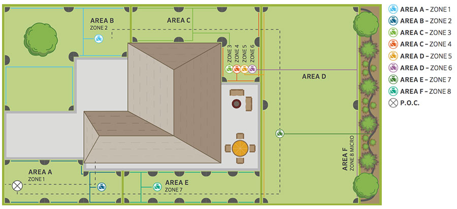
Now we go back to our plan and divide the emitters into the required number of zones. The goal is to make the flow of each zone as balanced as possible without exceeding the 55 L/min limit.
- Zone 1 (Sprinklers): Group half of the sprinklers, preferably those in a contiguous area (e.g., the front lawn).
- 16 heads × 2.8 L/min = 44.8 L/min. (This is < 55 L/min, so it's good).
- Zone 2 (Sprinklers): Group the remaining sprinklers (e.g., the back and side lawns).
- 16 heads × 2.8 L/min = 44.8 L/min. (Also < 55 L/min).
- Zone 3 (Drip): All drip emitters go on this single zone.
- Total flow = 18.8 L/min. (Well below our limit).
You would now mark this on your design plan, using different colors or labels for each zone.
Step 4: Locate the Valves
The final step is to decide where to place the control valves for these zones. You have two main options:
- Manifold: Group all the valves together in one or more valve boxes. This makes them easy to find, wire, and service. It is the most common method for residential projects.
- Remote: Place each valve individually out in the landscape, close to the zone it controls. This can reduce the length of lateral pipe needed but makes locating and servicing the valves more difficult.
To see a practical example of a valve manifold, let's watch a short clip.
Designing Landscape Irrigation | DIYers can do it too!
The 'Designing Landscape Irrigation' video by Yard Coach shows a clear, color-coded example of a five-valve manifold system.
Watch the segment from 05:29 to 06:50. The presenter explains his zoning decisions: three valves for the lawn (sprinklers) and two for the planter beds (drip), all grouped in one location. This is a perfect illustration of the zoning process we just completed.
Conclusion
Congratulations! You have now bridged the gap between the physical layout and the hydraulic system. By organizing all your emitters into logical zones, you have created a design that is efficient, protects your plants, and works within the physical limitations of your water supply.
Key Takeaways:
- What is a Zone? A group of emitters controlled by a single valve.
- The Golden Rules of Zoning:
- The total flow of a zone must be less than the available water supply.
- Never mix different sprinkler types or sprinklers with drip on the same zone.
- Align hydraulic zones with hydrozones (plant type, sun, slope).
- The Zoning Process: Group by component type, calculate total flows, divide by available flow to find the number of zones, and then distribute emitters to create balanced zones on your plan.
In our next lesson, we will do a final check on our design by focusing on the most challenging parts of the villa project: we'll refine our layout strategies for scattered shrubbery using individual drippers and perfect the sprinkler patterns for the most irregularly shaped lawn areas. This ensures our component placement is fully optimized before we move on to pipe sizing and hydraulic calculations.