Hello! In our last lesson, you performed a full hydraulic analysis on our capstone project's most demanding zone. You calculated the total friction loss and the Total Dynamic Head (TDH) required, confirming that the available water pressure is sufficient to operate that zone. That was a critical verification step.
Today, we'll build on that process to complete a core design task. This lesson addresses the learning outcome: Size all main and lateral pipes for the entire irrigation system on the plan. We will move from analyzing one zone to systematically determining the correct pipe diameter for every part of our villa project. This ensures efficient water delivery, prevents system damage, and optimizes material costs.
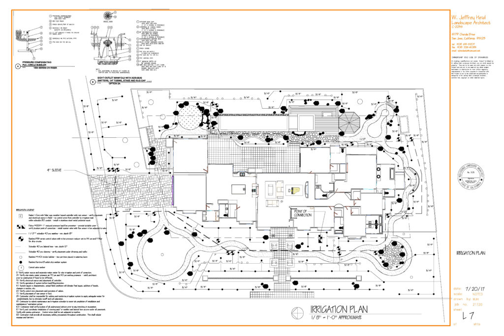
By the end of this lesson, you will be able to apply a systematic, table-based method to select the appropriate pipe size for every mainline and lateral line in your irrigation plan. The final result will look something like this, with every pipe clearly sized.
1. The Guiding Principle of Pipe Sizing: Water Velocity
The most important factor in pipe sizing is the velocity of the water, measured in feet per second (fps) or meters per second (m/s). If water moves too fast through a pipe, it can create surges and shockwaves known as "water hammer," which can damage fittings, valves, and sprinkler heads.
The industry-standard rule is to keep water velocity below 5 feet per second (approximately 1.5 m/s).
Fortunately, you don't need to calculate velocity for every pipe manually. The friction loss charts we will be using are designed with this rule in mind.
Pipe Size Matters - How to Read Irrigation Friction Loss Charts
To understand how to use these charts effectively, watch this excellent explanation from 'Sprinkler Nerd Andy'. He clearly demonstrates how to read the charts and emphasizes the '5 feet per second' rule.
Watch from the beginning to 9:10. Pay close attention to: The explanation of the '5 feet per second' rule (around 2:00). How the charts are laid out with flow rate (GPM) on the left and pipe sizes in the columns. How the shaded areas on the chart represent velocities above 5 fps, acting as a 'no-go' zone.
As you saw, the charts make it simple: to size a pipe correctly, you find your flow rate and select the smallest pipe size that is not in the shaded area.
2. Sizing the Mainline
The mainline is the backbone of your system. It runs from the water source (Point of Connection or POC) to the solenoid valves for each zone. Since only one zone will run at a time, the mainline only needs to handle the flow rate of a single zone.
To size the mainline, you must size it for the zone with the highest flow rate.
Let's continue with our villa project. Assume our zones have the following total flow rates:
- Zone 1 (Lawn): 30 GPM
- Zone 2 (Shrubs): 12 GPM
- Zone 3 (Trees/Drip): 8 GPM
The highest flow rate is 30 GPM from Zone 1. Therefore, we must size our entire mainline to handle 30 GPM.
Let's use the Hunter Friction Loss Chart for Class 200 PVC (found in the Irrigation Hydraulic.. document from your resources) to find the correct size.
- Find 30 GPM in the far-left "Flow GPM" column.
- Move across that row to the right.
- The first pipe size that is not shaded is 1-1/2" pipe.
- At 30 GPM, a 1-1/4" pipe has a velocity of 5.22 fps (shaded, too high).
- At 30 GPM, a 1-1/2" pipe has a velocity of 3.98 fps (in the white, acceptable).
Decision: The mainline for this project should be 1-1/2" Class 200 PVC.
3. Sizing the Lateral Lines
Lateral lines run from the zone valve to the sprinkler heads. Unlike the mainline, the flow rate in a lateral line is not constant. It decreases after each sprinkler head. This allows us to potentially use smaller pipe sizes for sections with lower flow, a technique that can reduce material costs, especially on larger projects.
The method is to work backwards from the furthest sprinkler on the line to the zone valve, adding up the flow as you go.
The Hunter Design Guide provides a clear, step-by-step procedure for this exact process. This is the standard industry method for sizing lateral lines.
Please read the section titled 'Pipe Sizing' (page 109). Focus on the sub-section 'Pipe Sizing Using the Friction Loss Tables', specifically the steps for 'Lateral Lines'. This outlines the backward-calculation method we will now apply.
Worked Example: Sizing the Lateral for Zone 1
Let's apply this method to our Zone 1 layout from the previous lesson. We have five heads (A-E), each with a flow of 6 GPM. The pipe is Class 200 PVC.
This is the diagram we will use for our calculations, showing the pipe sections A, B, C, and D connecting the sprinkler heads. The flow accumulates as we move from the last sprinkler back toward the valve. (Image Source: Hunter Industries)
We will build a simple table to track our sizing decisions.
| Pipe Section | Sprinklers Supplied | Flow (GPM) | Min. Pipe Size (Class 200) | Notes |
|---|---|---|---|---|
| A | Furthest Head | 6 | 3/4" | Velocity (1.67 fps) is well below 5 fps. |
| B | Two Heads | 12 | 1" | 3/4" pipe at 12 GPM is too high (5.56 fps). |
| C | Three Heads | 18 | 1-1/4" | 1" pipe at 18 GPM is too high (6.44 fps). |
| D | Four Heads | 24 | 1-1/4" | Velocity (4.52 fps) is acceptable. |
| (Valve-D) | All Five Heads | 30 | 1-1/2" | 1-1/4" pipe at 30 GPM is too high (5.22 fps). |
Let's walk through the decisions:
- Section A: Supplies one head (6 GPM). On the chart, 3/4" pipe works perfectly.
- Section B: Supplies two heads (12 GPM). Looking at the 12 GPM row, the 3/4" column is shaded (velocity > 5 fps). We must move to the next size up: 1".
- Section C: Supplies three heads (18 GPM). The 1" column is shaded. We move to 1-1/4".
- Section D: Supplies four heads (24 GPM). The 1-1/4" column is not shaded (velocity is 4.52 fps). It's acceptable, so we can stick with 1-1/4".
- Section to Valve: Supplies all five heads (30 GPM). The 1-1/4" column is now shaded. We must upsize to 1-1/2".
Your final lateral pipe design for Zone 1 would be a series of telescoping sizes: the final section is 3/4", then 1", then two sections of 1-1/4", and finally 1-1/2" connecting to the valve. You would then mark these sizes on your irrigation plan.
Test your understanding!
You are sizing a lateral line for a small shrub zone with three spray heads. The pipe is Class 200 PVC.
- The furthest head uses 2 GPM.
- The middle head uses 2 GPM.
- The head closest to the valve uses 3 GPM.
Using the friction loss charts, what is the minimum pipe size for each of the three pipe segments, working backward from the last head?
Show answer
- Segment 1 (to furthest head): Flow = 2 GPM. A 3/4" pipe is more than sufficient. (In practice, pipe smaller than 3/4" is rarely used for laterals).
- Segment 2 (to middle head): Flow = 2 GPM (furthest) + 2 GPM (middle) = 4 GPM. A 3/4" pipe is still fine.
- Segment 3 (to first head/valve): Flow = 4 GPM + 3 GPM (closest) = 7 GPM. A 3/4" pipe is still acceptable (velocity is 3.18 fps).
For this small zone, you could simply use 3/4" pipe for the entire lateral line. Downsizing is most beneficial when flow rates are high and require larger, more expensive pipe sizes.
Conclusion
You have now learned the systematic process for sizing every pipe in your irrigation system. This is the final step in the hydraulic design phase, ensuring your paper plan translates into a functional reality.
Key Takeaways:
- The primary goal of pipe sizing is to keep water velocity below 5 fps (1.5 m/s) to prevent water hammer.
- Friction loss charts are your main tool, with shaded areas indicating velocities that are too high.
- Mainlines are sized based on the single highest flow rate of any zone in the system.
- Lateral lines are sized by working backward from the last head to the valve, accumulating flow at each step. This allows for cost-saving by downsizing pipes where possible.
In our next and final lesson of this capstone project, we will use our completed design to tackle the operational side. Now that we have a hydraulically sound system with correctly sized pipes, we can accurately calculate irrigation runtimes, develop a schedule for the controller, and produce the final deliverables: the annotated plan and a complete Bill of Quantities (BOQ).