Hello! Welcome to your final lesson in the "Continuum and Fluid Mechanics" module.
In our last lesson, we derived the exact solution for laminar flow in a pipe, known as Hagen-Poiseuille flow. We saw how simplifying the Navier-Stokes equations under specific assumptions can yield powerful, practical results like Poiseuille's law. We also introduced the Reynolds number as a critical parameter for determining the flow regime—laminar, transitional, or turbulent.
Today, we will build on these concepts to explore the forces a fluid exerts on an object moving through it. This is the heart of aerodynamics and hydrodynamics. Our goal is to solve problems involving lift and drag forces on objects in a fluid flow, including boundary layer concepts.
Specifically, we will:
- Define lift and drag forces and their origins in pressure and shear stress.
- Explore the crucial role of the boundary layer, the thin layer of fluid near the object's surface.
- Understand the difference between laminar and turbulent boundary layers and their impact on drag.
- Investigate flow separation and its dramatic effect on pressure drag.
- Mathematically connect lift to the concept of circulation via the Kutta-Joukowski theorem.
This topic is fundamental to countless engineering applications, from designing efficient aircraft and cars to understanding the forces on submarines and even sports balls. Your background in calculus will be essential as we integrate stresses and explore the mathematical models governing these forces.
1. Defining Lift and Drag
When a fluid flows past an object, it exerts a force. This resultant force is conventionally resolved into two components:
- Drag (): The component of the force parallel to the direction of the upstream fluid flow.
- Lift (): The component of the force perpendicular to the direction of the upstream fluid flow.
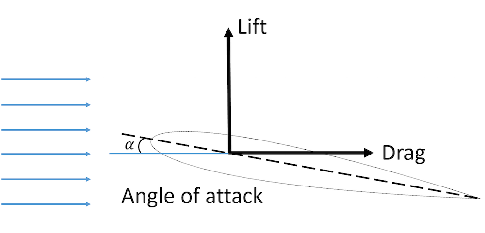
To understand where these forces come from, we need to look at the fluid's interaction with the object's surface.
Understanding Aerodynamic Drag
First, let's get a clear visual and conceptual overview of drag and its sources. This video from 'The Efficient Engineer' provides an excellent introduction.
Watch from the beginning to 2:31. Pay close attention to: The definition of lift and drag as components of the total fluid force. The two types of stress that act on the surface: shear stress (tangential) and pressure stress (perpendicular). How these stresses lead to two distinct types of drag: friction drag and pressure drag.
As the video explains, the total drag force is the sum of two contributions:
- Friction Drag (or Skin Drag): Caused by the shear stresses () acting tangentially on the object's surface due to the fluid's viscosity.
- Pressure Drag (or Form Drag): Caused by the distribution of pressure () acting perpendicularly on the surface. This is due to the shape, or "form," of the body.
The total drag is the integral of the components of these stresses in the direction of flow over the entire surface area of the body.
2. The Boundary Layer: The Arena of Drag
Both friction and pressure drag are governed by the behavior of the fluid in a thin region near the object's surface called the boundary layer. This is where the effects of viscosity are dominant.
To understand the boundary layer in more detail, we'll consult a chapter from a fluid dynamics textbook. This will provide the rigorous foundation you appreciate.
Read the introduction (section 25) and section 25.1 'Physics of boundary layers' (pages 509-511). Focus on: Prandtl's concept: At high Reynolds numbers, viscous effects are confined to a thin layer. The no-slip condition at the wall. The estimate for laminar boundary layer thickness, \delta \sim L / \sqrt{Re_L}. The definition of wall shear stress, \sigma_{wall}, and its relation to skin drag.
Key Concepts of the Boundary Layer:
- Formation: Due to the no-slip condition, the fluid velocity at the object's surface is zero (relative to the object). The velocity then rapidly increases across the thin boundary layer until it matches the "freestream" velocity, , of the main flow.
- Thickness (): The thickness of this layer is not constant. For a flat plate in a uniform flow, it grows with the distance from the leading edge: . This means the boundary layer gets thicker as the flow moves along the body.
- Laminar vs. Turbulent: Like pipe flow, the boundary layer can be laminar or turbulent.
- Laminar Boundary Layer: The flow is smooth and orderly. The velocity profile is parabolic (similar to Poiseuille flow near the wall). Friction drag is dominant for highly streamlined bodies.
- Turbulent Boundary Layer: The flow is chaotic and features significant mixing. This mixing brings higher-momentum fluid closer to the surface, resulting in a "fuller" velocity profile and a much higher wall shear stress. Consequently, turbulent boundary layers produce more friction drag than laminar ones.
3. Flow Separation and Pressure Drag
For blunt bodies (like a sphere, or an airfoil at a high angle of attack), pressure drag is often the dominant component of total drag. The primary cause of high pressure drag is flow separation.
Understanding Aerodynamic Drag
Let's return to 'The Efficient Engineer' video to visualize flow separation and its consequences.
Watch from 2:31 to 5:22. This section masterfully explains: The concepts of favorable and adverse pressure gradients. How an adverse pressure gradient (flow slowing down) can cause the boundary layer to detach or 'separate' from the surface. The creation of a large, low-pressure wake behind the object, which is the direct cause of high pressure drag. The counter-intuitive idea that a turbulent boundary layer, due to its higher energy, can resist separation better than a laminar one, thus reducing pressure drag.
This phenomenon explains the "drag crisis" for spheres and cylinders. At a critical Reynolds number, the boundary layer transitions from laminar to turbulent before the separation point. This turbulent layer remains attached to the surface longer, moving the separation point further back. This results in a much smaller wake and a dramatic drop in pressure drag, which more than compensates for the increase in friction drag. This is why golf balls have dimples—to deliberately trigger a turbulent boundary layer to reduce overall drag.
The shape of the object is key.
- Streamlined bodies (like an airfoil at a small angle of attack) are designed to minimize pressure drag by keeping the flow attached for as long as possible. For these, friction drag is the main concern.
- Blunt bodies (like a flat plate perpendicular to the flow) cause massive flow separation, and their drag is almost entirely pressure drag.
4. Calculating Drag Force: The Drag Equation
While integrating pressure and shear stress is the fundamental method, it's often impractical. A more common engineering approach uses the drag equation, which bundles the complex effects of shape, viscosity, and flow regime into a single dimensionless number: the drag coefficient ().
Understanding Aerodynamic Drag
The next segment of the video introduces the drag equation and the drag coefficient.
Watch from 9:36 to 13:52. Focus on: The Drag Equation: F_D = C_D \frac{1}{2} \rho V^2 A. What the drag coefficient C_D represents. How C_D depends on the object's shape and the Reynolds number (Re). The example of Stokes' Law for a sphere at very low Re.
The drag equation is:
Where:
- is the drag coefficient, which depends on the shape of the body and the Reynolds number. It is usually determined experimentally (e.g., in a wind tunnel) or via numerical simulation.
- is the fluid density.
- is the freestream velocity.
- is a characteristic reference area (e.g., frontal area for blunt bodies, planform area for wings).

Test your understanding!
A car has a drag coefficient and a frontal area . It is traveling at 108 km/h (which is 30 m/s). The density of air is approximately .
- Calculate the aerodynamic drag force on the car.
- The power required to overcome this drag is . Calculate this power in kilowatts (kW).
Show answer
-
Drag Force:
First, apply the drag equation: -
Power to Overcome Drag:
This shows that a significant portion of a car's engine power at highway speeds is used just to overcome air resistance.
5. The Generation of Lift: Circulation and the Kutta-Joukowski Theorem
Now let's turn to lift. While drag is often a necessary evil, lift is usually the goal, especially in aeronautics. Lift is also generated by pressure differences, but in this case, it's the pressure difference between the top and bottom surfaces of an object like an airfoil.
A powerful mathematical concept for quantifying lift is circulation, denoted by the Greek letter Gamma (). Circulation represents the net rotational "strength" of the flow around an object. The fundamental relationship between lift and circulation is given by the Kutta-Joukowski Theorem.
Kutta Joukowski theorem [Aerodynamics #10]
This video provides an excellent mathematical derivation of the Kutta-Joukowski theorem, starting from basic principles. It demonstrates how adding a vortex (circulation) to a uniform flow creates the velocity difference needed for lift.
Watch from 0:53 to 14:49. This is a detailed segment, so focus on the following key stages of the argument: Conceptual Introduction (0:53 - 2:46): Understand the core idea: combining a uniform flow with a vortex flow models a lifting flow. Mathematical Derivation (2:46 - 11:44): Follow the steps of the proof. This is a great example of applying core principles. He starts with the velocity field, uses Bernoulli's equation to find the pressure, and then integrates the pressure forces around the cylinder to find the net lift and drag. The Result and its Generality (11:44 - 14:49): Pay close attention to the final equation and the crucial point that although derived for a cylinder, the theorem applies to any lifting body, like an airfoil.
The Kutta-Joukowski theorem states that the lift per unit span () on a two-dimensional body is directly proportional to the fluid density (), the freestream velocity (), and the circulation () around the body:
This elegant theorem is a cornerstone of aerodynamics. It shows that in order to generate lift, there must be a net circulation of flow around the lifting body. This circulation is what causes the flow to be faster over the top surface and slower on the bottom.
How does an airfoil generate circulation?
An airfoil is shaped and angled (angle of attack) such that it "guides" the flow, forcing more air over its longer, curved upper surface. To prevent an unphysical flow condition at the sharp trailing edge, a circulation is naturally established around the airfoil, resulting in a smooth flow off the trailing edge (the Kutta condition). This circulation is precisely what's needed to generate lift.
6. Engineering Applications: Using and Managing Flow Phenomena
Understanding lift, drag, and boundary layers allows engineers to design systems that manipulate these forces.
3: Additional Aerodynamics Tools
The 'Additional Aerodynamics Tools' text discusses two excellent examples of applying these principles in aircraft design: winglets and leading-edge strakes.
Please read Sections 3.4 'Wings (3-D Aerodynamics)' and 3.5 'Vortex Aerodynamics: Winglets' and 3.6 'Vortex Aerodynamics: Leading Edge Vortex'. In Section 3.4, focus on the concepts of wingtip vortices, downwash, and induced drag. Note the formula for induced drag coefficient: C_{Di} = C_L^2 / (\pi \text{AR} e). In Sections 3.5 and 3.6, see how these vortex phenomena, which cause induced drag, can be harnessed to create benefits. Note how winglets use the wingtip vortex flow to generate thrust, and how leading-edge strakes create stable vortices to maintain lift at high angles of attack.
-
Induced Drag and Winglets: A finite wing has high pressure on the bottom and low pressure on top. At the wingtips, the high-pressure air tries to flow around to the low-pressure side, creating wingtip vortices. This swirling motion alters the airflow over the wing, creating a component of the aerodynamic force that points backward—this is induced drag. As the reading mentions, it is related to the lift coefficient squared (). Winglets are small, vertical extensions on the wingtips that interact with this vortex flow, effectively using its energy to generate a small forward thrust component, reducing the overall induced drag and improving fuel efficiency.
-
Vortex Lift: Highly swept wings, like those on fighter jets, can intentionally create a stable vortex that starts at the leading edge and flows over the top of the wing. This is the leading-edge vortex. The extremely low pressure inside this vortex "sucks" on the wing, generating significant "vortex lift." This allows the aircraft to achieve very high angles of attack without stalling, enabling extreme maneuverability. This effect is often enhanced with leading-edge extensions (LEX) or strakes, as seen on fighters like the F/A-18.
Conclusion
This lesson has provided an overview of the fundamental forces governing motion through a fluid. We have seen that lift and drag are not simple phenomena but are the result of complex interactions within the boundary layer.
Key Takeaways:
- Drag Force is composed of Friction Drag (from viscous shear at the surface) and Pressure Drag (from pressure differences, mainly due to flow separation).
- The Boundary Layer is the region where viscous effects are critical. Its state—laminar or turbulent—determines the magnitude of friction drag and the point of flow separation.
- Flow Separation occurs in an adverse pressure gradient, creating a low-pressure wake that is the primary source of pressure drag on non-streamlined bodies.
- Lift Force is fundamentally linked to Circulation through the Kutta-Joukowski Theorem ().
- Engineering designs like winglets and strakes are clever applications of fluid dynamics principles to manipulate vortices, reducing drag and enhancing lift.
Preview of the Next Lesson:
This concludes our deep dive into Continuum and Fluid Mechanics. We have built a strong foundation from the kinematics of continua to the complexities of the Navier-Stokes equations and their applications. We will now pivot to a new, but related, branch of physics. In the next module, "Thermodynamics," our first lesson will be to "Apply the First Law of Thermodynamics to analyze work, heat, and internal energy changes in various processes." We will see how energy conservation governs the behavior of systems at a macroscopic level, a principle that is deeply connected to the energy considerations we've touched upon in fluid dynamics.