Hello! Welcome to your third lesson in the "Continuum and Fluid Mechanics" module.
In our last lesson, we established the constitutive relationship for linear elastic isotropic materials—the Generalized Hooke's Law. We saw how the stress tensor is linearly related to the strain tensor through two independent elastic constants, such as Young's Modulus and Shear Modulus .
Today, we will apply these fundamental principles to solve some of the most classic and important problems in structural engineering. This lesson is designed to address the learning outcome: Derive and apply the equations for bending, torsion, and buckling of beams in engineering contexts. We will see how the abstract concepts of stress, strain, and elastic moduli manifest in the real-world behavior of structural members.
Our journey today is divided into three parts, each tackling a distinct mode of deformation:
- Bending (Flexure): How beams support loads by bending.
- Torsion: How shafts transmit power by twisting.
- Buckling: How slender columns can suddenly fail under compression.
Let's begin.
1. Bending of Beams: Euler-Bernoulli Theory
Beams are structural elements designed to support loads applied transversely to their longitudinal axis. Bridges, aircraft wings, and floor joists are all examples of beams. When a beam is loaded, it deflects. To analyze this, we use the Euler-Bernoulli beam theory, which is built on a few key assumptions.
Solid Mechanics Theory | Euler-Bernoulli Beams
This first video segment from Dr. Clayton Pettit's 'Solid Mechanics Theory | Euler-Bernoulli Beams' series introduces the theory and its foundational assumptions. Understanding these assumptions is crucial as they define the limits of the theory's applicability.
Watch from the beginning to 3:34. Pay close attention to the four main assumptions of Euler-Bernoulli beam theory that are listed.
To summarize the key assumptions from the video:
- Small deformations: The beam's deflections are small compared to its length.
- Linear elastic isotropic material: The material obeys Hooke's law and has uniform properties in all directions.
- Poisson's ratio effects are ignored: This is a simplification that is valid for slender beams.
- Plane sections remain plane and normal to the longitudinal axis: This is the most critical kinematic assumption. It dictates the geometry of deformation.

Deriving the Bending Equations
The power of the "plane sections remain plane" assumption is that it allows us to derive the strain, and consequently the stress, at any point in the beam. The following video provides a rigorous derivation, and since you appreciate mathematical formalism, I encourage you to follow each step closely.
Solid Mechanics Theory | Euler-Bernoulli Beams
This segment of the video derives the core relationships for beam bending, starting from the geometric assumption and applying Hooke's Law. This is a masterful application of the principles we've studied.
Please watch from 7:29 to 21:29. The derivation is detailed, so focus on the logical flow: (7:29 - 16:56) See how the geometric assumption leads to a linear strain distribution across the beam's height: \epsilon_{11} = -x_2 rac{d^2y}{dx_1^2}. (Note: the video uses x_1 for the longitudinal axis and x_2 for the vertical axis from the centroid). Then, see how Hooke's law (\sigma_{11} = E \epsilon_{11}) is applied to find the stress. (16:56 - 21:29) Observe how the internal bending moment M is calculated by integrating the stress over the cross-sectional area. This culminates in the fundamental moment-curvature relationship: M = EI rac{d^2y}{dx_1^2}.
Let's summarize the results. If we let be the longitudinal axis and be the vertical deflection, and we place the origin at the centroid of the cross-section:
- The normal strain along the beam is , where is the local radius of curvature.
- The normal stress is .
- For small deflections, . This gives the flexure formula for stress:
where is the second moment of area of the cross-section about the neutral axis. This formula is paramount in beam design. Notice that for a given moment , the stress is maximum at the points farthest from the neutral axis (largest ). This is why I-beams are so efficient: they place most of their material far from the centroid to resist bending stress effectively.
The Governing Equation for Beam Deflection
To find the deflection of a beam, we need to relate the bending moment to the applied load . This is done through equilibrium analysis on a differential element of the beam.
Solid Mechanics Theory | Euler-Bernoulli Beams
These final clips from the same video derive the relationships between distributed load, shear force, and bending moment, and then assemble everything into a single governing differential equation for beam deflection.
First, watch from 3:23 to 7:29 to see the derivation of dM/dx = V (shear force) and dV/dx = -q (distributed load). Then, watch from 21:18 to 22:45 where these are combined with the moment-curvature relation to get the final fourth-order equation.
The key relationships are:
Combining these, we get .
Substituting our moment-curvature relationship (assuming constant flexural rigidity ), we arrive at the celebrated Euler-Bernoulli beam equation:
This fourth-order ordinary differential equation is the starting point for calculating the deflection of a beam under a distributed load . Solving it requires four boundary conditions (e.g., specifying deflection and slope at the ends).
2. Torsion of Circular Shafts
Next, we consider torsion—the twisting of a member due to an applied torque. This is the primary mechanism for power transmission in rotating machinery like engine driveshafts and axles.
For this analysis, we will focus on shafts with a circular cross-section. This is a crucial specialization, because circular shafts under torsion behave very cleanly: their cross-sections rotate as rigid disks without distorting (warping). This is not true for non-circular shafts (e.g., square or rectangular), whose analysis is more complex.
The video 'Understanding Torsion' by The Efficient Engineer provides a beautifully clear and concise derivation of the key torsion formulas.
Watch from the beginning to 7:13. The video is very efficient. Follow the logical progression: (0:00 - 3:05) Definition of torsion and derivation of the angle of twist formula \phi = rac{TL}{GJ}. Note the roles of Shear Modulus G and the Polar Moment of Inertia J. (3:05 - 7:13) Derivation of the shear strain and shear stress distributions, leading to the torsion stress formula au = rac{Tr}{J}. The explanation of why hollow shafts are more efficient at carrying torque is a key engineering insight.
The derivation rests on a geometric assumption analogous to the one in beam theory:
- The shear strain varies linearly from the center of the shaft: , where is the total angle of twist over length .
- Applying Hooke's law in shear, , gives the shear stress distribution: .
- Integrating the torque produced by this stress over the cross-section yields the total torque .
This process results in two fundamental equations for torsion:
- Angle of Twist:
- Shear Stress:
Here, is the polar moment of inertia, a geometric property of the cross-section representing its resistance to twisting. For a solid circular shaft of radius , .
Notice the beautiful analogy between the bending and torsion equations:
- Bending: Involves Moment , Young's Modulus , and Second Moment of Area .
- Torsion: Involves Torque , Shear Modulus , and Polar Moment of Inertia .
3. Buckling of Columns
Our final topic is buckling, a failure mode characterized by a sudden sideways deflection of a slender structural member subjected to high compressive load. Unlike yielding, which is a material failure, buckling is a failure of stability. A column can buckle even when the compressive stress is well below the material's yield strength.
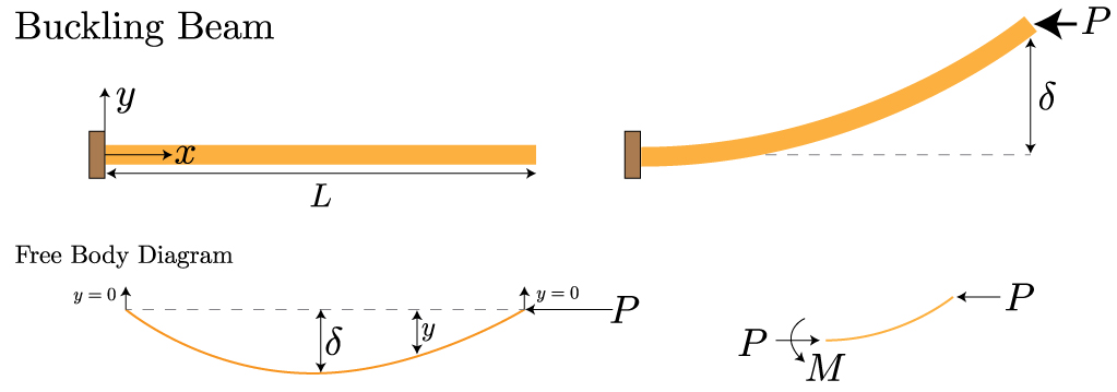
We will derive the critical buckling load for the most fundamental case: a pin-ended column, often called an Euler Column.
The derivation involves finding the load at which the column can be in equilibrium in both a straight and a slightly bent configuration. Consider the column in a slightly bent shape . The internal bending moment at any point is generated by the axial force acting on the moment arm :
The negative sign arises from the sign convention for bending moment (a positive deflection creates a "hogging" or negative moment).
We can now use the moment-curvature relationship we derived in the bending section, :
Rearranging gives the governing differential equation for an axially loaded column:
This is a second-order linear homogeneous ODE with constant coefficients. As you know from your calculus course, this is the equation for simple harmonic motion.
To see the formal solution and the emergence of the critical load, please read the following section from a textbook on structural stability.
The document 'Buckling of Columns' provides a formal derivation of the Euler buckling load for a pin-ended column. It demonstrates how solving the governing differential equation and applying boundary conditions leads to a specific, critical value for the load.
Read Section 1.3, 'EULER LOAD' (pages 4-6). Start from the derivation of Eq. (1.3.2), which we already established, and follow the solution through to Eq. (1.3.6). Pay attention to how the boundary conditions (y=0 at both ends) force the solution to be non-trivial only for specific values of the load P.
As the text derives, solving the ODE and applying the pin-end boundary conditions ( and ) shows that a non-trivial (i.e., bent) solution only exists if:
This condition is met when for an integer .
Solving for gives the possible buckling loads:
The lowest load at which buckling can occur corresponds to . This is the Euler Critical Buckling Load:
This famous formula shows that the resistance to buckling depends on the material's stiffness and the beam's geometric resistance to bending , and it is inversely proportional to the square of the length. This is why long, slender columns are much more susceptible to buckling.
For other boundary conditions (e.g., fixed-fixed, cantilevered), the same equation applies but with an effective length replacing . For example, a column with two fixed ends is much more stable, having an effective length of , which quadruples its critical buckling load.
Test your understanding!
You have two columns of the same length, made from the same amount of the same material (i.e., they have the same cross-sectional area). Column A has a solid square cross-section (side length ). Column B has a hollow circular cross-section (a thin-walled tube). Which column do you expect to be more resistant to buckling, and why?
Show answer
Column B, the hollow circular tube, will be more resistant to buckling.
The critical buckling load is proportional to the second moment of area, . The formula is . To resist buckling, we want to maximize the minimum value of for the cross-section, since the column will buckle about its weakest axis.
For a given amount of material (area ), the most efficient way to maximize the second moment of area is to distribute that material as far as possible from the centroidal axis. A hollow tube does this much more effectively than a solid square. Most of the tube's material is located at a large radius, contributing significantly to , whereas much of the square's material is near the center, contributing little.
Therefore, for the same area , the hollow circular section will have a significantly larger than the solid square section, resulting in a higher critical buckling load.
Conclusion
In this lesson, we have derived the foundational equations governing three critical behaviors of structural members. You've seen how the continuum mechanics principles of stress, strain, and Hooke's Law are applied to create powerful, predictive engineering models.
Key Takeaways:
- Bending: Governed by the Euler-Bernoulli equation . Bending stress is given by . Resistance is dictated by the flexural rigidity, .
- Torsion: For circular shafts, the angle of twist is , and shear stress is . Resistance is dictated by the torsional rigidity, .
- Buckling: A stability failure for slender columns. The critical compressive load for a pin-ended column is , again depending on the flexural rigidity .
Preview of the Next Lesson:
We have now completed our initial foray into solid mechanics. In the next lesson, we will pivot to the second major theme of this module: fluid mechanics. We will begin by deriving one of the most fundamental principles in fluid dynamics: the continuity equation, which is an expression of the conservation of mass for a fluid flow.