Hello! Welcome to your next lesson in Electrodynamics.
In our previous lesson, we characterized the inductor as a circuit element that opposes changes in current, governed by the relationship , and stores energy in its magnetic field. We are now equipped to analyze circuits containing resistors, capacitors, and inductors.
Today's lesson fulfills the learning outcome: Analyze transient and steady-state behavior of RL, LC, and RLC circuits using ODEs. We will use Kirchhoff's laws to formulate ordinary differential equations (ODEs) that describe these circuits. By solving these equations, we will distinguish between the initial transient response and the long-term steady-state behavior. This analysis is fundamental to electronics and provides a powerful, practical application of the differential equations you are studying.
We will begin with first-order (RL and RC) circuits to establish the method, then move to the more complex second-order RLC circuit, where we'll find a direct and powerful analogy to the damped harmonic oscillators you've studied in mechanics.
1. First-Order Circuits: The Transient Response
First-order circuits contain one energy storage element (either an inductor or a capacitor) and a resistor. Their behavior is described by a first-order linear ODE. Let's analyze the case where a DC voltage source is suddenly connected to the circuit.
The solution to these ODEs has two parts:
- The Homogeneous Solution (Transient Response): This part describes how the circuit naturally returns to equilibrium. It always decays exponentially to zero.
- The Particular Solution (Steady-State Response): This part describes the circuit's behavior after a long time has passed. For a DC source, it's the final, stable state.
The total solution is the sum of these two parts, with constants determined by the initial conditions of the circuit.
The RC and RL Circuits with a DC Source
Let's watch a video that derives and solves the governing ODEs for both RC and RL circuits when a DC voltage is applied. This will formalize the concepts of charging/discharging and the time constant.
Transient Analysis: First order R C and R L Circuits
This video from ALL ABOUT ELECTRONICS provides a step-by-step derivation for the response of RC and RL circuits to a DC voltage source. It clearly separates the transient (complementary function) and steady-state (particular integral) parts of the solution.
Please watch from 11:08 to 21:49. The first part covers the RC circuit, and the second covers the RL circuit. Focus on how Kirchhoff's Voltage Law leads to a first-order ODE in each case and how the total solution is constructed from the transient and steady-state parts.
As the video demonstrated, the governing equations are:
- RC Circuit:
- RL Circuit:
In both cases, the transient part of the solution decays as , where the time constant determines the speed of the decay:
- For an RC circuit, .
- For an RL circuit, .
After about , the transient response becomes negligible, and the circuit is considered to have reached its steady state.
2. Second-Order Circuits: The Series RLC Circuit
Now, let's add all three components—R, L, and C—in series with a voltage source . This creates a second-order system with richer and more complex behavior.
Applying Kirchhoff's Voltage Law (KVL) around the loop gives:
Substituting the V-I relationships , , and (so ), we get:
This is a second-order, linear, inhomogeneous ordinary differential equation. You should immediately recognize its form. It is mathematically identical to the equation for a damped, driven mechanical oscillator:
This is not just a coincidence; it's a deep physical analogy:
- Inductance () acts like mass (): It represents inertia, resisting changes in current (velocity).
- Resistance () acts like damping (): It dissipates energy.
- Inverse Capacitance () acts like the spring constant (): It stores potential energy.
- Charge () is analogous to position (), and Current () is analogous to velocity ().
The Transient Response of an RLC Circuit
The transient behavior is described by the homogeneous equation (setting ). We solve this by substituting an ansatz , which yields the characteristic equation:
The roots of this quadratic equation determine the nature of the transient response:
Just as with a mechanical oscillator, we have three distinct regimes depending on the values of R, L, and C.
To formalize this, we define two important parameters:
- Damping Factor:
- Natural (Resonant) Frequency:
The roots can then be written as .
The following video provides an excellent and comprehensive derivation of these three cases.
Transient Analysis of the RLC Circuit (with Examples)
This video from ALL ABOUT ELECTRONICS details the derivation of the RLC circuit's governing equation and meticulously explains the three damping regimes based on the roots of the characteristic equation.
Please watch from 0:48 to 13:21. Pay close attention to how the relationship between the component values (R, L, C) dictates whether the response is overdamped, critically damped, or underdamped. Note the corresponding graphical shapes of the response.
Let's summarize the three cases discussed in the video:
- Overdamped ():
- Condition: or .
- The characteristic equation has two distinct, real, negative roots.
- The solution is a sum of two decaying exponentials: .
- The system returns to equilibrium slowly and without any oscillation.
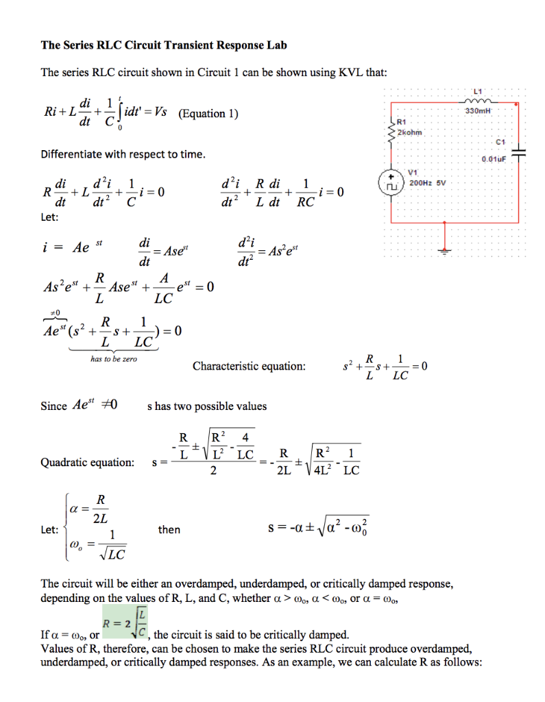
*This image shows the derivation of the RLC equation and the conditions for the three damping regimes, providing a concise mathematical summary.*
2. Critically Damped ():
* Condition: or .
* The characteristic equation has one repeated, real, negative root ().
* The solution has the form: .
* This is the "sweet spot" that provides the fastest return to equilibrium without any overshoot or oscillation. This is highly desirable in many engineering applications, like the suspension in a car or a closing automatic door.
- Underdamped ():
- Condition: or .
- The characteristic equation has two complex conjugate roots: , where is the damped frequency.
- The solution is a decaying sinusoid: .
- The system oscillates as it returns to equilibrium, with the amplitude of oscillations decaying exponentially. This is the behavior seen in radio tuners and filters.

*This image visually summarizes the underdamped case, showing the circuit, the governing equation, the form of the solution, and the characteristic decaying oscillatory waveform.*
3. Mathematical Rigor: The ODE Solution Method
Your preference for mathematical rigor is well-served by a deeper look into solving these ODEs. The text "Differential Equations for Engineers" provides a formal treatment that parallels our circuit analysis.
Differential Equations for Engineers - Math.HKUST
To solidify the mathematical foundation, please review these sections from 'Differential Equations for Engineers' by the HKUST Math Department. They cover exactly the theory of second-order ODEs we are applying.
First, read 'Lecture 13' through 'Lecture 18' (pages 31-41). This provides the complete theory for solving homogeneous second-order ODEs with constant coefficients, covering all three cases: distinct real roots (overdamped), complex-conjugate roots (underdamped), and repeated roots (critically damped). Then, quickly read 'Lecture 25' (page 57), which shows the direct application of this theory to the RLC circuit equation we just derived.
This reading confirms that the method for analyzing RLC circuits is a direct, robust application of the theory of ordinary differential equations.
4. Parallel RLC Circuits
The same principles apply to a parallel RLC circuit, but the analysis starts with Kirchhoff's Current Law (KCL). The resulting ODE has a similar second-order form, but the roles of R, L, and C in the coefficients are different. For instance, in a parallel circuit, a large resistance leads to less damping, because less current is diverted through the dissipative path. You can find a detailed derivation in the video "Transient Analysis of the RLC Circuit" from 13:21 to 18:43.
5. Solving a Complete Problem
Let's see how to solve for the transient current in a circuit, including finding the unknown constants using initial conditions. The initial conditions are based on the principles that:
- Inductor current cannot change instantaneously: .
- Capacitor voltage cannot change instantaneously: .
Watch one of the worked examples from the video we saw earlier.
Transient Analysis of the RLC Circuit (with Examples)
This example shows the full process for an underdamped parallel RLC circuit: setting up the equation, finding the roots, writing the general solution, and using initial conditions to find the specific solution.
Watch the second example from 24:43 to 29:15. Follow the steps used to solve for the voltage V(t).
Test your understanding!
Consider a series RLC circuit with , , and . The circuit is initially uncharged and has no current. At , it is connected to a V DC source.
- Determine if the circuit is overdamped, critically damped, or underdamped.
- Find the natural frequency and the damped frequency (if applicable).
- Write the general form of the solution for the charge on the capacitor, . You don't need to solve for the constants.
Show answer
-
Determine the damping regime:
- Calculate the damping factor: s.
- Calculate the natural frequency: rad/s.
- Since (), the circuit is underdamped.
-
Find the frequencies:
- Natural frequency rad/s.
- Damped frequency rad/s.
-
General solution form:
- The solution is the sum of the steady-state (particular) and transient (homogeneous) solutions.
- Steady-state: After a long time, the capacitor is fully charged, so C.
- Transient: For an underdamped circuit, this is a decaying sinusoid: .
- The full solution for the charge is:
The constants A and B would be found using the initial conditions and .
Conclusion
In this lesson, we have seen how the principles of circuit theory and differential equations combine to provide a complete description of RL, LC, and RLC circuits.
Key Takeaways:
- The behavior of RLC circuits is governed by second-order linear ODEs, which are analogous to the equations of a damped mechanical oscillator.
- The transient response is the solution to the homogeneous ODE and decays over time. Its character depends on the circuit's components.
- The three regimes of transient response are overdamped (slow, non-oscillatory decay), critically damped (fastest non-oscillatory decay), and underdamped (decaying oscillations).
- The steady-state response is the particular solution to the inhomogeneous ODE and describes the circuit's long-term behavior.
- The complete solution is the sum of the transient and steady-state responses, with constants determined by initial conditions.
Preview of the Next Lesson:
Our analysis today focused on the "lumped element" model, where fields are confined to ideal components. However, this model has its limits. A key piece is missing from Ampere's Law when fields are changing in time. In our next lesson, "Formulate the Ampère-Maxwell law by introducing the concept of displacement current," we will address this inconsistency. This will complete the full set of Maxwell's equations and pave the way for understanding one of the most profound discoveries in physics: electromagnetic waves.