Hello! Welcome to your next lesson in Electrodynamics.
In our last lesson, we established Faraday's Law, , revealing that a changing magnetic field creates a non-conservative electric field. This induced EMF is the driving force behind currents in circuits exposed to changing magnetic flux. Today, we will quantify this effect by defining the properties of self-inductance and mutual inductance.
Your learning outcome is to calculate mutual and self-inductance and analyze energy stored in magnetic fields. We will define these properties, learn how to calculate them for fundamental geometries like solenoids, and derive the expression for the energy stored in the magnetic field of an inductor. This lays the groundwork for treating inductors as circuit components, which is essential for our upcoming analysis of RLC circuits.
1. Self-Inductance: A Circuit's "Electrical Inertia"
When current flows through a wire loop, it creates a magnetic field, which in turn produces a magnetic flux through the loop itself. If this current changes, the flux changes, and by Faraday's Law, an EMF is induced in the loop. This phenomenon, where a circuit induces an EMF in itself to oppose a change in its own current, is called self-induction.
To get an intuitive feel for this, let's watch a short segment that introduces inductance as a form of "electrical inertia."
EMI JEE L4 | 𝐒𝐞𝐥𝐟 & 𝐌𝐮𝐭𝐮𝐚𝐥 𝐈𝐧𝐝𝐮𝐜𝐭𝐚𝐧𝐜𝐞 | Class 12 Physics | JEE 2022 | Path Finder | Vedantu Enthuse
This clip from Vedantu JEE English explains why an inductor resists changes in current, much like mass resists changes in velocity in mechanics.
Please watch from 5:56 to 11:25. Focus on the analogy between mechanical inertia (mass) and electrical inertia (inductance). Note how inductance opposes the change in current, not the current itself.
Formal Definition and Back-EMF
As the video explained, the magnetic flux produced by a circuit is directly proportional to the current flowing through it. The constant of proportionality is the self-inductance, denoted by .
For a coil with turns where the flux through each turn is , the total flux linkage is , so we write . The unit of inductance is the Henry (H), where .
Now, applying Faraday's Law, the induced EMF (often called "back-EMF") is:
This is the fundamental voltage-current relationship for an inductor. The negative sign, a manifestation of Lenz's Law, shows that the induced EMF opposes the change in current:
- If (current is increasing), is negative, opposing the current flow.
- If (current is decreasing), is positive, trying to sustain the current flow.
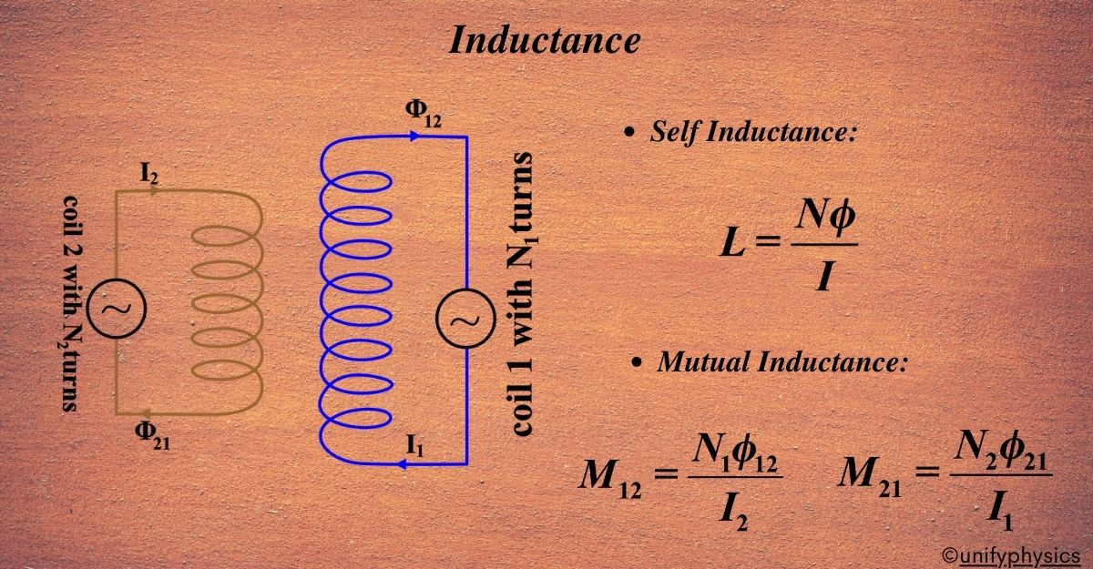
Calculating Self-Inductance
Inductance is a purely geometric property of a conductor, depending on its size, shape, and the number of turns. It does not depend on the current. To calculate it:
- Assume a current flows through the conductor.
- Use Ampere's Law or the Biot-Savart Law to find the magnetic field produced by this current.
- Calculate the total magnetic flux passing through the circuit.
- The self-inductance is then .
Let's see this procedure applied to the classic case of a long solenoid.
EMI JEE L4 | 𝐒𝐞𝐥𝐟 & 𝐌𝐮𝐭𝐮𝐚𝐥 𝐈𝐧𝐝𝐮𝐜𝐭𝐚𝐧𝐜𝐞 | Class 12 Physics | JEE 2022 | Path Finder | Vedantu Enthuse
The following part of the Vedantu video provides a clear, step-by-step derivation for the self-inductance of a solenoid.
Watch the segment from 24:06 to 29:03. Follow the derivation, which calculates the magnetic field, the flux through one turn, the total flux linkage, and finally finds L.
As derived, for a long solenoid of length , radius , and turns per unit length (total turns ), the self-inductance is:
where is the cross-sectional area.
2. Energy Stored in a Magnetic Field
To establish a current in an inductor, the power source must do work against the back-EMF. This work is stored as potential energy in the inductor's magnetic field.
The power delivered to the inductor is .
The differential work done to increase the current by in time is:
To find the total energy stored when the current increases from 0 to , we integrate:
This is the energy stored in an inductor. Given your background, this derivation should feel analogous to finding the kinetic energy of a mass, , by integrating the work done, .
Energy Density of the Magnetic Field
A more fundamental perspective, which aligns with your goal of studying theoretical physics, is to consider the energy as being stored in the magnetic field itself. The energy per unit volume, or magnetic energy density , is given by:
The total energy is the integral of this density over all space: .
Let's verify that these two energy formulas, and , are consistent for our solenoid example.
- Inside a long solenoid, . The field is approximately zero outside.
- The volume of the solenoid is .
- The total energy from energy density is .
- Recognizing the term in the parenthesis as the inductance of the solenoid, we get .
The two approaches yield the same result. This gives us a second powerful method to calculate inductance: find the total magnetic energy from the B-field and set it equal to .
Test your understanding!
For a deeper dive into these concepts, let's turn to a high-level resource. The following document from the Physics Olympiad Handouts provides a rigorous and concise summary.
This text, 'Electromagnetism V: Induction' by Kevin Zhou, is aimed at Physics Olympiad preparation. It formalizes the concepts we've discussed and presents them at the level of rigor you prefer.
Please read 'Idea 5' on page 15 and 'Example 5' on page 16. This covers the magnetic field energy formula and its application to find the self-inductance of a solenoid, which we just discussed.
Now, apply this knowledge. Consider a toroidal solenoid (a solenoid bent into a circle) with a rectangular cross-section of height and width , turns, and an inner radius .
- Calculate its self-inductance by first finding the magnetic field inside the toroid (for ) using Ampere's Law, then calculating the total flux .
- Separately, calculate the total magnetic energy by integrating the energy density over the volume of the toroid. Verify that your result is consistent with using the you found in part 1.
(This is Problem 17 (a) and (b) from the handout you just reviewed.)
Show answer
-
Inductance from Flux:
- Ampere's Law for a loop of radius inside the toroid gives , so .
- The flux through one turn is .
- Total flux is .
- Inductance is .
-
Energy Verification:
- The energy is .
- .
- Comparing with , we substitute our from part 1:
. - The results match perfectly.
3. Mutual Inductance: Coupled Circuits
Now, consider two coils placed near each other. A changing current in Coil 1 produces a changing magnetic field. Some of this field's flux, , passes through Coil 2, inducing an EMF . This is mutual induction.
The flux through Coil 2 is proportional to the current in Coil 1:
The induced EMF in Coil 2 is:
where is the mutual inductance of coil 2 with respect to coil 1.
A remarkable and non-obvious result, known as the reciprocity theorem, states that the mutual inductance is symmetric: . The flux produced in coil 1 by a current in coil 2 is related by the same constant .
Let's watch a conceptual introduction and a sample calculation for coaxial solenoids.
EMI JEE L4 | 𝐒𝐞𝐥𝐟 & 𝐌𝐮𝐭𝐮𝐚𝐥 𝐈𝐧𝐝𝐮𝐜𝐭𝐚𝐧𝐜𝐞 | Class 12 Physics | JEE 2022 | Path Finder | Vedantu Enthuse
We'll return to the Vedantu video to introduce mutual inductance and see how it's calculated for a pair of nested solenoids.
First, watch from 57:50 to 1:03:30 for the conceptual introduction to mutual inductance. Then, skip to 1:12:17 and watch until 1:17:35 for the derivation of mutual inductance between two coaxial solenoids. Note how the calculation depends on the geometry, specifically the area of the inner solenoid.
The calculation procedure is analogous to that for self-inductance. For two coaxial solenoids, with the inner solenoid having radius and turns/length, and the outer having turns/length, the mutual inductance over a common length is:
Notice that it's the smaller area that determines the flux linkage.
4. Energy in Magnetically Coupled Circuits
When multiple inductors are coupled, the total stored energy includes a term for the mutual inductance. For two coupled inductors with currents and , the total energy is:
The sign of the mutual term depends on the relative direction of the magnetic fields produced by the currents.
- Positive sign (+): Used when the currents produce fluxes that add to each other (aiding).
- Negative sign (-): Used when the currents produce fluxes that oppose each other.
This is often tracked using a "dot convention" in circuit diagrams, which we will explore when analyzing AC circuits. For now, understanding the physical basis of aiding/opposing fluxes is key. For a formal derivation of this energy expression, the following video provides a clear walkthrough.
Electrical Engineering: Ch 14 Magnetic Coupling (20 of 55) Energy with Mutual Coupling
This short video by Michel van Biezen provides a clear, step-by-step derivation of the total energy stored in a pair of mutually coupled inductors.
Watch the entire video. It first reviews the energy of a single inductor and then builds up the expression for two coupled inductors, explaining the origin of the mutual energy term M I_1 I_2.
5. Application and Challenge
Engineering Application: The Transformer
Mutual inductance is the operating principle of the transformer, a crucial component in electrical power distribution. A transformer consists of two coils, a primary and a secondary, wound on a common iron core.
- An alternating current (AC) in the primary coil creates a time-varying magnetic flux.
- The iron core guides nearly all of this flux through the secondary coil.
- The changing flux induces an AC voltage in the secondary coil via mutual induction.
If the flux linkage is perfect, the ratio of the voltages is equal to the ratio of the number of turns: . This allows for efficient stepping-up or stepping-down of AC voltages.
Olympiad-Level Challenge
Here is a problem that combines the concepts of self-inductance, mutual inductance, and conservation laws, typical of a physics competition.
Let's look at one final problem from the 'Electromagnetism V: Induction' handout to test your integrated understanding.
Read 'Problem 24' on page 27. You don't need to solve it immediately, but think about the physical principles you would use.
Hint: Superconducting rings have zero resistance. This implies that the magnetic flux through the area of a superconducting ring cannot change. If an external field tries to change the flux, a current will be induced in the ring to create an opposing field that keeps the total flux constant. You will need to write down two flux conservation equations (one for each ring) involving the initial current , the final currents and , and the self- and mutual-inductances and .
Conclusion
Today, we've formalized the consequences of Faraday's Law in circuits, defining the key properties of inductance.
Key Takeaways:
- Self-Inductance () measures a circuit's tendency to oppose changes in its own current, defined by and resulting in a back-EMF .
- Mutual Inductance () measures the flux linkage between two circuits, defined by and inducing an EMF . It is symmetric ().
- Inductance is a geometric property.
- The energy stored in an inductor is . This energy resides in the magnetic field with a density of .
- For coupled inductors, the total energy includes a mutual term: .
Preview of the Next Lesson:
We have now fully characterized the inductor as a circuit element. In our next lesson, we will combine it with resistors and capacitors to analyze RL, LC, and RLC circuits. This will involve setting up and solving the ordinary differential equations that describe the transient and steady-state behavior of these fundamental electronic systems.