Welcome back. In our first lesson, we built a foundational, physical intuition for voltage, current, resistance, and power. We established that voltage is the "pressure," current is the "flow," and resistance is the "opposition" in an electrical circuit.
Now, we will translate that conceptual understanding into a quantitative one. This lesson focuses on Ohm's Law, the simple yet powerful mathematical formula that connects voltage, current, and resistance. Mastering this law is the first major step toward analyzing, predicting, and designing circuits—moving from simply knowing what the components are to knowing exactly how they will behave. This is where your journey into the engineering of electronics truly begins.
The Core Relationship: Ohm's Law
Ohm's Law states that the voltage across a resistor is directly proportional to the current flowing through it. The constant of proportionality is the resistance. This relationship is the cornerstone of DC circuit analysis.
The law is expressed in a beautifully simple equation:
Where:
- is the voltage, measured in Volts (V).
- is the current, measured in Amperes (A).
- is the resistance, measured in Ohms (Ω).
The image below illustrates a basic circuit where Ohm's Law applies. A voltage source () pushes a current () through a resistor (), causing power () to be dissipated.
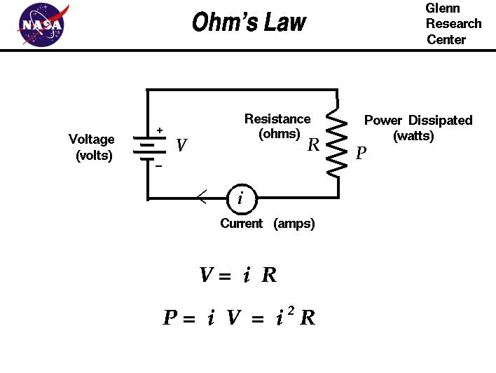
A simple circuit diagram showing a voltage source (V), a resistor (R), and the resulting current (i). The formulas for Ohm's Law and power are displayed below.
For a more dynamic introduction and a handy mnemonic, the following video is excellent.
Ohms Law Explained - The basics circuit theory
Watch this segment from "Ohms Law Explained" by The Engineering Mindset. It clearly introduces the three forms of the Ohm's Law equation and the "Ohm's triangle," a useful tool for remembering them.
Watch the first part of the video, which covers the three formulas and the mnemonic triangle.
By rearranging the primary formula, we can solve for any of the three variables if we know the other two:
- To find current:
- To find resistance:
This algebraic manipulation is straightforward, but its implications are profound. It means we can determine the precise behavior of a simple circuit before we even build it.
Ohm's Law: The Basics of Electrical Circuits
This text from ROHM technical articles provides a concise summary of the law, its equations, and the proportional relationships.
Read the first two sections. Start with the introduction, paying attention to the VRI Triangle visual aid. Then, continue to the section on Current, Voltage, and Resistance to reinforce the proportionalities.
Understanding the Proportions
Thinking about Ohm's Law in terms of proportionality is key to developing an intuitive feel for circuit behavior.
- Current is directly proportional to voltage: If you keep the resistance constant and double the voltage, the current will also double. More "pressure" results in more "flow."
- Current is inversely proportional to resistance: If you keep the voltage constant and double the resistance, the current will be cut in half. More "opposition" results in less "flow."
The same video from The Engineering Mindset provides excellent animated examples that make these relationships very clear.
Ohms Law Explained - The basics circuit theory
Continue watching "Ohms Law Explained". These segments demonstrate how changing one variable affects the others in a circuit, visually reinforcing the concepts of direct and inverse proportionality.
First, watch the example of finding voltage and how it affects current. Next, see the example of finding current and how resistance affects it. Finally, watch the segment on finding resistance.
Applying the Law: Calculation Examples
Let's put this into practice. The following reading contains several worked-out examples. We will focus on a few key ones that demonstrate the direct application of the formulas.
2.7 Resistors and Ohm’s Law – Applied Electrical Engineering Fundamentals
This chapter from Applied Electrical Engineering Fundamentals provides clear, step-by-step examples of Ohm's Law calculations.
Please start at the "Examples" heading. Work through the first example, Figure 2.60, which is a straightforward calculation of voltage and power. Next, carefully read the solution for Figure 2.61. This example is important because it highlights the significance of current direction relative to voltage polarity, a concept known as the passive sign convention. Voltage drops in the direction of current flow. Finally, study the Example Problem for Figure 2.67. This ties everything together for a simple battery and resistor circuit.
A Core Engineering Task: The Current-Limiting Resistor
One of the most common applications of Ohm's Law in embedded systems is calculating the value of a current-limiting resistor for a Light-Emitting Diode (LED).
An LED is not a simple resistor. It's a semiconductor diode that emits light when current flows through it. It has two key properties we must respect:
- A relatively fixed forward voltage drop (): This is the voltage the LED "consumes" when it's on (e.g., ~2V for a red LED).
- A maximum forward current (): This is the ideal current for proper brightness without damaging the LED (e.g., 20mA).
If you connect an LED directly to a voltage source like a 5V supply, the voltage is too high and the current will be uncontrolled, instantly destroying the LED. We must add a resistor in series to "absorb" the excess voltage and limit the current to a safe level.
Here's the process:
- Determine the voltage the resistor must "drop": .
- Use Ohm's Law to find the resistance needed to achieve the desired current: .
For example, to power a red LED (, ) from a 5V source:
This calculation is fundamental. You will perform it constantly when interfacing microcontrollers with LEDs.
How To Select The Resistor Value In a LED Circuit Using Ohm's Law
This video from The Organic Chemistry Tutor is a fantastic, practical guide to exactly this calculation.
Watch from the beginning to understand why a resistor is needed. Pay close attention to the worked example for a single LED. Finally, the video discusses how to calculate the power dissipated by the resistor. This is critical for choosing a resistor that won't burn out.
Power Dissipation in Resistors
As we just saw, when a resistor limits current, it converts electrical energy into heat. The rate of this energy conversion is power. In the last lesson, we learned the primary power formula:
By substituting Ohm's Law into this equation, we get two other extremely useful forms:
Why is this important? Every physical resistor has a power rating (e.g., 1/4 Watt, 1/2 Watt). If you force it to dissipate more power than its rating, it will overheat, its resistance value may change, and it will eventually fail—often releasing the "magic smoke" that makes electronics work. As an engineer, you must always calculate the power your resistor will dissipate to ensure you choose a component that can handle the load safely.
Conclusion
In this lesson, you have moved from concepts to calculations. You now possess the primary tool for analyzing simple DC circuits.
Key Takeaways:
- Ohm's Law provides the mathematical relationship between voltage, current, and resistance: .
- The law can be rearranged to solve for any of the three variables: and .
- Current is directly proportional to voltage and inversely proportional to resistance. This allows you to reason about how a circuit will behave.
- A critical practical application is calculating the value of a current-limiting resistor, essential for components like LEDs.
- Power dissipated by a resistor ( or ) must be calculated to select components that operate safely within their power ratings.
So far, we have only considered circuits with a single resistive element. Real-world circuits are rarely this simple. In our next lesson, we will build upon Ohm's Law to analyze circuits containing multiple resistors connected in series and in parallel, learning how to calculate their combined "equivalent resistance."