Hello! In our last lesson, we established that the Spanning Tree Protocol (STP) is essential for building resilient, loop-free switched networks. You learned that STP achieves this by logically blocking redundant links, transforming a physically looped topology into a stable, tree-like structure.
Today, we'll dive into the specific mechanics of how STP makes these decisions. We will explore the step-by-step process of electing a central "root bridge" and then look at the different states a switch port transitions through as the network converges. Mastering this process is key to predicting network behavior and troubleshooting Layer 2 issues for your project.
Step 1: The Root Bridge Election
The entire Spanning Tree topology is built around a single, central switch called the root bridge. All other switches in the network calculate their best path to this root bridge. The election process is democratic but definitive: the switch with the numerically lowest Bridge ID (BID) wins and becomes the root.
A switch's Bridge ID is composed of two parts:
- Bridge Priority: A configurable value.
- MAC Address: A unique, hard-coded address.
Initially, every switch boots up and declares itself the root bridge by sending out special STP frames called Bridge Protocol Data Units (BPDUs). When switches receive BPDUs from their neighbors, they compare the incoming BID with their own. If a switch receives a BPDU with a lower (superior) BID, it stops advertising itself as the root and begins forwarding the superior BPDU instead. This process continues until all switches agree on which one has the absolute lowest BID in the network.
The following video from Jeremy's IT Lab provides an excellent, detailed explanation of the Bridge ID and the election process.
Free CCNA | Spanning Tree Protocol (Part 1) | Day 20 | CCNA 200-301 Complete Course
This segment from "Free CCNA | Spanning Tree Protocol (Part 1)" focuses on the root bridge election.
Watch from the root bridge election. As you watch, pay close attention to these key points: How the Bridge ID is formed from the priority and the MAC address. The default priority value and how the MAC address acts as a tie-breaker. The concept of the extended system ID, where the VLAN number is added to the priority. This is why the default priority for VLAN 1 is actually 32769 (32768 + 1). Why the priority value can only be changed in increments of 4096.
As you saw in the video, the modern Bridge ID is actually a combination of a 4-bit priority field and a 12-bit VLAN ID (the extended system ID), which together form a 16-bit priority value, plus the 48-bit MAC address.
Since the default priority is 32768 on all Cisco switches, the election is typically decided by the VLAN ID and then the lowest MAC address. To influence the election and make a more powerful or central switch the root bridge, an administrator can manually lower its priority value.
Step 2: Electing Port Roles
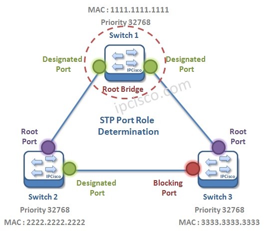
Once the root bridge is elected, the network is oriented. The next step for STP is to determine the role of every other port in the network to build a single, loop-free path from every switch to the root bridge. There are three main roles a port can take:
- Root Port (RP): Every non-root switch selects one root port. This is the port on the switch with the fastest, lowest-cost path to the root bridge. All root ports are placed in a forwarding state.
- Designated Port (DP): Every network segment (the link between two switches) has one designated port. This is the port responsible for forwarding traffic onto that segment. All ports on the root bridge are designated ports. Designated ports are also placed in a forwarding state.
- Non-Designated Port (NDP): Also called an Alternate or Blocking Port. If a port is not a root port or a designated port, it becomes a non-designated port. It is put into a blocking state to break the loop. It does not forward data but will listen for BPDUs to know when to take over if a primary link fails.
The selection of these roles is a deterministic process based on cost and a series of tie-breakers.
Free CCNA | Spanning Tree Protocol (Part 1) | Day 20 | CCNA 200-301 Complete Course
The next part of the Jeremy's IT Lab video explains how switches select their root ports and then their designated ports.
First, watch the section on Root Port selection. Focus on understanding the concept of STP cost based on link speed (memorize these values!) and the three tie-breakers: Lowest cumulative Root Cost to the root bridge. Lowest neighbor Bridge ID. Lowest neighbor Port ID. Next, watch the segment on Designated Port selection. This explains how the final decision is made on links that don't lead directly to the root, resulting in one port being blocked.
Let's summarize the STP election algorithm:
- Elect the Root Bridge: Lowest Bridge ID wins.
- Elect Root Ports (on non-root switches):
- The port with the lowest Root Cost wins.
- Tie-breaker 1: The port receiving the BPDU from the neighbor with the lowest Bridge ID.
- Tie-breaker 2: The port receiving the BPDU from the neighbor with the lowest Port ID.
- Elect Designated Ports (on each segment):
- The port on the switch with the lowest Root Cost wins.
- Tie-breaker 1: The port on the switch with the lowest Bridge ID.
- Tie-breaker 2: The port with the lowest Port ID.
- Block Remaining Ports: Any port that is not a Root Port or a Designated Port is put into a blocking state.
STP Port States
A port doesn't instantly transition from blocking to forwarding. To prevent temporary loops during a topology change, STP moves ports through a series of states, each with a specific purpose and duration. This is why you see an amber light on a switch port for about 30 seconds after plugging in a cable before it turns green.
There are five port states:

Spanning Tree Protocol STP Tutorial
This section from the "Spanning Tree Protocol STP Tutorial" provides a concise and clear table summarizing the port states.
Find the section titled "STP switch port states" and review the descriptions and the summary table. Focus on what each state does regarding forwarding data and learning MAC addresses.
Let's walk through the transitions for a port destined to forward traffic:
- Blocking: The port starts here. It receives BPDUs but does not send BPDUs, forward user data, or learn MAC addresses. If STP determines this port should not be part of the active topology, it remains in this stable state.
- Listening: If STP decides the port can become a root or designated port, it transitions to listening. Here, it can send and receive BPDUs to participate in the election process, but it still doesn't forward data or learn MACs. This state lasts for the Forward Delay timer, which is 15 seconds by default.
- Learning: After 15 seconds in the listening state, the port moves to learning. It continues to send and receive BPDUs and now begins to learn MAC addresses from frames it receives, populating its MAC address table. However, it still does not forward any frames. This state also lasts for the 15-second Forward Delay timer.
- Forwarding: Finally, after the learning phase, the port enters the forwarding state. It is now fully operational: it sends/receives BPDUs, learns MAC addresses, and forwards user data frames.
- Disabled: This state is for ports that are administratively shut down. They do not participate in STP at all.
The total time to move a port from blocking to forwarding is typically 30 seconds (15s listening + 15s learning). If a link fails, the network must wait for the Max Age timer (20 seconds) to expire before starting this transition, leading to a total convergence time of up to 50 seconds. This significant delay is a major drawback of classic STP.
Conclusion
In this lesson, you explored the detailed mechanics of the Spanning Tree Protocol. You now have a solid understanding of how switches elect a root bridge and assign port roles to create a loop-free path, and the sequence of states a port moves through during this process.
Key Takeaways:
- STP elects a single root bridge based on the lowest Bridge ID (Priority + MAC Address).
- All other switches determine their root port (best path to the root) and designated ports based on path cost and a series of tie-breakers. Any remaining ports are blocked.
- Ports transition through five states: Disabled, Blocking, Listening, Learning, and Forwarding.
- The transition from blocking to forwarding for classic STP takes about 30 seconds (15s Listening + 15s Learning), which can lead to slow network convergence after a topology change.
In our next lesson, we will examine Rapid Spanning Tree Protocol (RSTP), an evolution of STP designed to dramatically reduce this convergence time, making the network far more responsive to changes.