Hello! In our previous lesson, we explored the critical trade-off between an AI agent's autonomy and the system's transparency, establishing architectural principles like "least agency" and "strong observability" to create governable systems. We designed safety nets to manage individual agents. But what happens when the whole is more chaotic than the sum of its parts?
Even with perfectly designed agents, their interactions can give rise to unexpected and often undesirable system-level outcomes. A minor error in one agent can trigger a chain reaction, leading to a full-blown failure cascade. This is the challenge of emergent behavior in complex systems.
Today, we will address this head-on. Our learning goal is to analyze a multi-agent system scenario to identify potential emergent behaviors and failure cascades using causal loop diagrams. We will shift our perspective from the individual component to the interconnected system, employing a powerful tool from systems thinking to visualize, diagnose, and ultimately preempt these complex failures. This is the final step in understanding the deep architectural challenges of multi-agent systems before we move on to broader strategic integration.
From Individual Faults to Systemic Failures
Before we can map out system-level behavior, we need a clear vocabulary for the individual faults that can occur. Much like having a catalog of error codes, a taxonomy of failures allows us to pinpoint the specific nodes of weakness in a multi-agent system.
Recent research has culminated in a structured framework for this, known as the Multi-Agent System Failure Taxonomy (MAST). This taxonomy categorizes the common ways these systems break down.
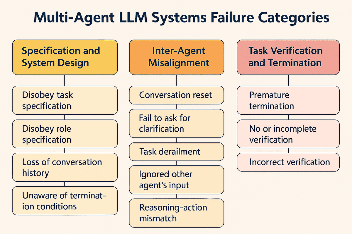
Let's dive into the foundational paper that introduced this taxonomy to get a more precise understanding of these failure modes.
Why Do Multi-Agent LLM Systems Fail?
This paper from arXiv provides a rigorous, data-driven analysis of why multi-agent systems fail. It introduces the MAST taxonomy, which we will use as the basis for our analysis.
Please read the following sections to familiarize yourself with the landscape of multi-agent failures: Read the Introduction (pages 1-2) to understand the motivation behind this research. Skim Section 4, "The Multi-Agent System Failure Taxonomy" (first paragraph), to get an overview. Carefully review the descriptions of the three main Failure Categories (FC): FC1. System Design Issues (Insight 1) FC2. Inter-Agent Misalignment (Insight 2) FC3. Task Verification (Insight 3) Finally, browse Appendix A, "MAST Failure Categories: Deep Dive" (pages 17-18), to see the precise definitions of all 14 failure modes. You don't need to memorize them, but get a feel for the types of issues identified.
As the paper and your own experience with distributed systems suggest, these failures are rarely isolated incidents. A "System Design Issue" like an ambiguous task specification can easily lead to "Inter-Agent Misalignment," as agents develop conflicting interpretations. This, in turn, can cause a "Task Verification" failure when the final output is checked against the wrong criteria. This chain reaction is a failure cascade. The Orq.ai blog post "Why Multi-Agent LLM Systems Fail" explains this dynamic well.
Why Multi-Agent LLM Systems Fail: Key Issues Explained - Orq.ai
This article provides a great summary of how individual failures connect to cause larger, systemic problems.
Please read the section titled Underlying Causes. Pay close attention to the concepts of Compounding Errors and Misaligned Goals.
These compounding errors and misaligned goals are classic examples of emergent behavior. To analyze—and predict—them, we need a tool that specializes in visualizing interconnectedness and feedback: the Causal Loop Diagram.
Introducing Causal Loop Diagrams (CLDs)
Causal Loop Diagrams (CLDs) are a cornerstone of systems thinking. They help us move beyond linear cause-and-effect and visualize the complex, circular relationships that drive system behavior. For an architect, they serve a purpose similar to sequence diagrams for interactions, but for feedback dynamics rather than message flows.
Let's watch a short video that introduces the core concepts of CLDs.
Systems Thinking: Causal Loop Diagrams
This video by Dr. Donna Gurule provides a clear and concise introduction to the building blocks of Causal Loop Diagrams.
Please watch the following segments to learn the fundamentals: Introduction (first segment): Understand the purpose of CLDs and their basic components: variables, links, polarities, and delays. Polarity (next segment): Learn how to determine if a causal link is positive (+) (variables move in the same direction) or negative (-) (variables move in opposite directions). Feedback Loops (third segment): Grasp the two fundamental types of loops: Reinforcing (R) loops, which amplify change, and Balancing (B) loops, which counteract change and seek stability. Delays (final segment): Understand the importance of delays, represented by hash marks (//), which indicate that an effect is not instantaneous.
To summarize the key concepts for our context:
- Variables: These are the factors in our system. We will use the failure modes from the MAST taxonomy (e.g., "Task Derailment," "Incorrect Verification") as our variables.
- Links & Polarity: An arrow from variable A to variable B indicates A causes a change in B.
- A
+sign means they move together: more A leads to more B; less A leads to less B. - A
-sign means they move opposite: more A leads to less B; less A leads to more B.
- A
- Reinforcing (R) Loops: These are amplifiers. In our analysis, they often represent vicious cycles where failures compound. They are identified by having an even number of negative links (or zero).
- Balancing (B) Loops: These are stabilizers. They represent self-correcting mechanisms or external controls that push the system back towards a desired state. They have an odd number of negative links.

Modeling a Multi-Agent Failure Scenario
Now, let's combine the MAST taxonomy with CLDs to analyze a concrete scenario.
Scenario: A multi-agent system for automated code refactoring.
- An Architect Agent identifies areas for refactoring in a codebase.
- A Coder Agent implements the refactoring.
- A Tester Agent runs tests to verify the changes.
Let's model a potential failure cascade.
1. Identify Key Variables:
We'll select a few relevant failure modes from the MAST taxonomy:
Ambiguity in Architect's Plan(a form of FM-1.1: Disobey task specification)Coder Ignores Tester Feedback(FM-2.5: Ignored other agent's input)Incomplete Test Coverage(a form of FM-3.2: No or incomplete verification)Bugs IntroducedHuman Architect Intervention(our balancing force)
2. Map the Causal Links:
Let's trace the relationships:
- An increase in
Ambiguity in Architect's Planleads to an increase inBugs Introducedby the Coder Agent, who misinterprets the goal. This is a positive link (+).
Ambiguity in Architect's Plan→+Bugs Introduced - An increase in
Bugs Introducedleads to an increase in necessaryHuman Architect Intervention. This is also a positive link (+).
Bugs Introduced→+Human Architect Intervention
3. Identify Feedback Loops:
Now, let's see how the system feeds back on itself.
A Vicious Cycle (Reinforcing Loop)
What if the Coder and Tester agents are misaligned?
- High
Incomplete Test Coveragemeans fewer bugs are caught. This has a negative link (-) to the detection of bugs. Let's call the detected bugsBugs Found. So,Incomplete Test Coverage→-Bugs Found. - If the Coder Agent consistently
Ignores Tester Feedback(perhaps due to poor prompt design), then even when bugs are found, they aren't fixed. Let's model this:Bugs Foundhas a negative relationship with the number of bugs that make it to production, but if the coder ignores the feedback, this link is broken. - Let's consider a different dynamic. The more the
Coder Ignores Tester Feedback, the moreBugs Introducedpersist. This is a positive link. In frustration, the Tester Agent might reduce its efforts, leading to moreIncomplete Test Coverage. This creates a reinforcing loop of dysfunction.
Let's diagram a simpler, classic reinforcing loop:
- The
Coder Ignores Tester Feedback, which increases the number ofBugs Introducedinto the main branch (+). - More
Bugs Introducedincrease thePerceived Unreliability of Coder. - This
Perceived Unreliabilitymight cause the Tester's prompts to become more terse or critical, which in turn makes theCoder Ignores Tester Feedbackbehavior even more likely (+).
Here we have a loop: Coder Ignores Tester Feedback → Bugs Introduced → Perceived Unreliability → Coder Ignores Tester Feedback. With all positive links, this is a Reinforcing (R) Loop—a vicious cycle of deteriorating collaboration.
A Corrective Action (Balancing Loop)
How can we fix this? With human oversight.
- An increase in
Bugs Introducedleads to an increase inHuman Architect Intervention(+). Human Architect Intervention(e.g., refining the Coder's role prompt or forcing it to process the Tester's feedback) leads to a decrease in theCoder Ignores Tester Feedbackbehavior (-).- A decrease in this ignoring behavior leads to a decrease in
Bugs Introduced(+ link, but the input is decreasing).
This creates a Balancing (B) Loop. The rise in bugs triggers an intervention that counteracts the problem, stabilizing the system. The loop looks like this: Bugs Introduced → + Human Architect Intervention → - Coder Ignores Tester Feedback → + Bugs Introduced. With one negative link, the loop is balancing.
By mapping these loops, you, as an architect, can visually identify where your system is vulnerable to runaway failures (R-loops) and where your control mechanisms (B-loops) are placed to counteract them. Your goal is to design a system where balancing loops are stronger than the vicious cycles.
Conclusion
In this lesson, we ventured into the complex world of emergent behavior in multi-agent systems. We saw that well-behaved individual agents can combine to create unpredictable and failing systems. By adopting a systems thinking approach, we can begin to tame this complexity.
Key Takeaways:
- Multi-agent system failures are often interconnected, creating failure cascades where one small error is amplified.
- The MAST taxonomy provides a crucial vocabulary to identify specific failure points (e.g., disobeying specifications, inter-agent misalignment, incomplete verification).
- Causal Loop Diagrams (CLDs) are an architectural tool for visualizing the feedback dynamics between these failure modes.
- Reinforcing (R) loops highlight potential vicious cycles or areas of exponential decay, which are prime candidates for failure cascades.
- Balancing (B) loops represent the self-correcting or external control mechanisms that provide system stability. Analyzing them reveals how your system recovers from errors.
Preview of the Next Module:
This lesson concludes our deep dive into the technical architecture of AI-powered systems. We've journeyed from integrating basic AI components to designing complex, self-regulating multi-agent architectures.
Now, we will zoom out. In the final module, Strategic AI Integration and Capstone, we will shift our focus from how to build these systems to where, why, and when to deploy them within an organization. We'll discuss responsible AI principles, human oversight, and how to map AI capabilities to real business value, all in preparation for your final capstone project.