Hello! Welcome back to our hands-on 5G lab.
In our last lesson, we successfully installed and configured all the components for our 5G Standalone (SA) test network: the Open5GS core, the srsRAN gNB (base station), and the srsUE (user equipment). We prepared the configuration files and ensured all the software was ready to go.
Today, we bring that network to life. Our goal is to verify a 5G SA attach procedure using srsUE and Open5GS logs. We will launch the components in sequence and carefully examine the logs and console outputs to trace the journey of our simulated UE as it connects to the network. This process of understanding a "normal" connection is fundamental. Before you can effectively attack a system, you must first understand how it's supposed to work. Your experience with network analysis will be invaluable here as we dissect the communication flow.
A Guide to Our Network's Logs
Before we start, it's important to know where to look for information. Our distributed system generates logs in several places. The following resource is an excellent guide to making sense of them.
Open5GS and srsRAN 5G Network Log Analysis
This blog post, "Open5GS and srsRAN 5G Network Log Analysis", provides a detailed overview of the logging mechanisms for both Open5GS and srsRAN. It explains where logs are stored, how to interpret them, and how to capture network traffic.
Please read the sections "Open5GS Logging" and "srsRAN_Project Logging". Pay attention to the default log locations (e.g., /var/log/open5gs/), the different logging levels (info, debug, trace), and the commands for tailing logs and capturing packets with tcpdump. You don't need to memorize everything, but be aware of what's available.
To summarize, we will be looking at three main sources of information:
- Open5GS Logs: Located in
/var/log/open5gs/. Theamf.logis the most important for today's lesson, as the AMF orchestrates the UE's connection. - srsRAN gNB Console: The gNB will print live status updates to the terminal where it's running. This shows its connection to the core and interactions with the UE.
- srsUE Console: The UE also prints its status to the terminal, showing its search for a cell, the connection progress, and the final IP address assignment.
Step 1: Launch the 5G Core Network (Open5GS)
First, we need to start the core network. In the previous lesson, we used docker-compose to deploy Open5GS.
- Navigate to the
Open5GS-srsRAN/dockerdirectory from the guide we used last time. - Start the core network services:
docker-compose up -d - Now, let's watch the AMF log in a new terminal window. The
-fflag will "follow" the log, showing new entries as they appear.sudo tail -f /var/log/open5gs/amf.log
You should see initialization messages as the AMF starts up and prepares its interfaces. As described in the "5GC Network Function Startup" section of the log analysis guide, the AMF creates an NGAP server, and the other core components (SMF, UPF) establish their own connections. For now, the logs will be quiet, waiting for a base station to connect.
Step 2: Launch the gNB and Connect to the Core
Next, we'll start our srsRAN gNB. It will connect to the AMF in the core network.
- In a new terminal, navigate to the directory where you built the srsRAN Project (
srsRAN_Project/build/). - Start the gNB using the configuration file we prepared in the last lesson.
(Note: Adjust the path to yoursudo ./apps/gnb/gnb -c ../../gnb_zmq.yamlgnb_zmq.yamlfile if you placed it elsewhere.)
Now, observe both the gNB's terminal and the AMF log you are tailing.
- In the gNB terminal: You should see a series of initialization steps, followed by a crucial message confirming its connection to the core. The srsRAN documentation we reviewed previously shows what to look for:
NG connection successful ==== gNodeB started ==== - In the
amf.logterminal: You will see a flurry of new activity. The AMF log will show that it has accepted an incoming N2 connection from the gNB's IP address and completed the NG Setup procedure. This establishes the control plane link between the radio network and the core.
This two-way confirmation tells us the gNB is operational and successfully registered with the core network. It is now broadcasting its cell information (MIB and SIB1), waiting for a UE.
Step 3: Launch the UE and Verify the Attach Procedure
This is the main event. We will now start the srsUE and trace its entire registration and connection process through the logs.
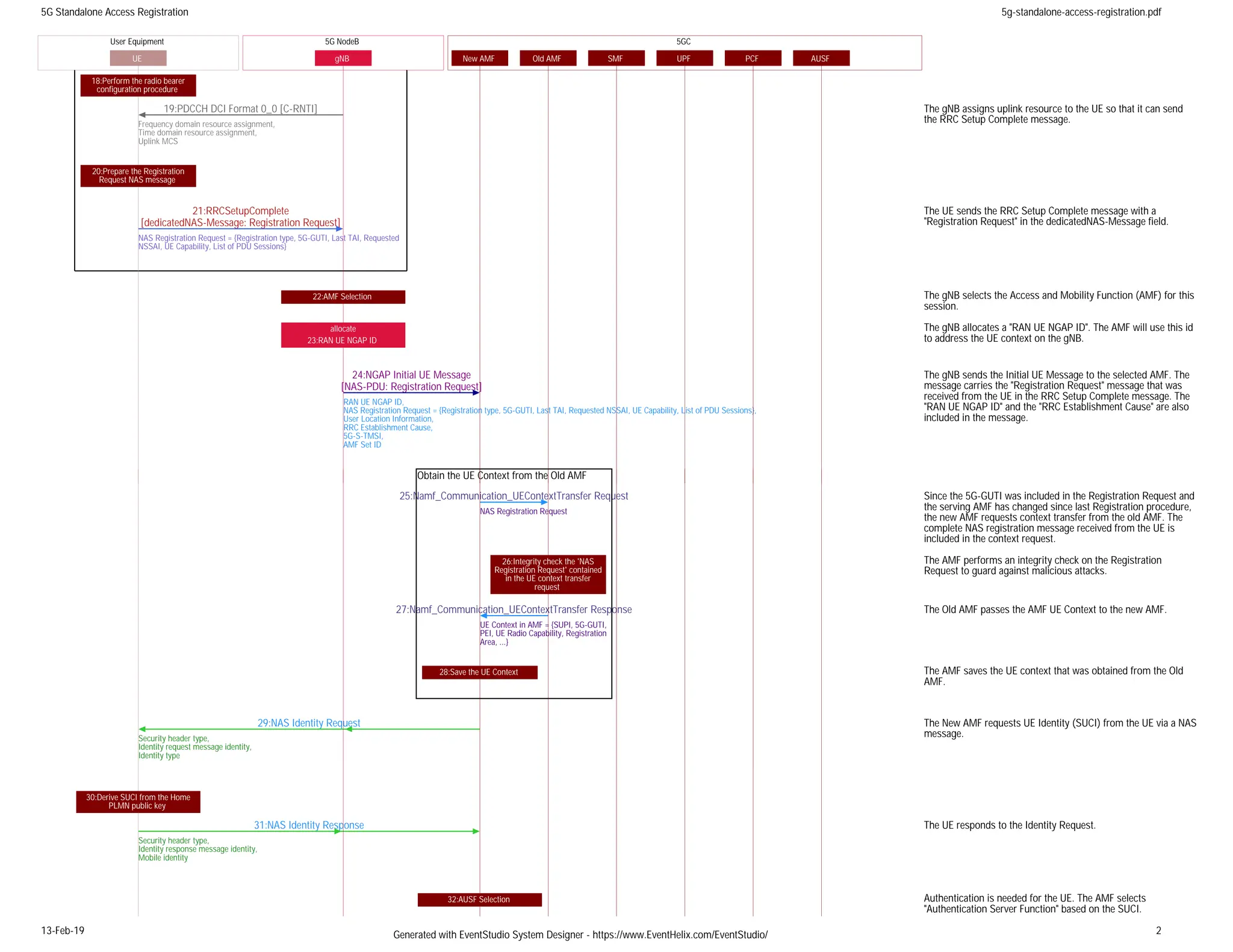
To help visualize the process, refer to this sequence diagram. It shows the standard messages exchanged between the UE, gNB, and AMF during a 5G SA registration. We will look for evidence of these steps in our logs.
- In a final terminal window, navigate to your srsRAN 4G build directory (
srsRAN/build/). - Start the UE, pointing it to its configuration file:
(Note: Adjust the path tosudo ./srsue/src/srsue -c ../ue_zmq.confue_zmq.confas needed.)
Keep an eye on all three terminals (UE, gNB, and AMF log). Here is the sequence of events you should observe, corresponding to the attach procedure:
| Step | Action | What to Look For |
|---|---|---|
| 1. Cell Search | The UE scans for 5G cells. | UE Console: Shows it is searching for a cell and then finds one with a specific PCI (e.g., PCI: 1). It synchronizes and decodes the MIB/SIB. |
| 2. RRC Connection | The UE establishes a Radio Resource Control (RRC) connection with the gNB. | gNB Console: Shows a "RACH procedure successful" message, followed by logs indicating an RRC setup with a new UE. |
| 3. NAS Registration | The UE sends a Registration Request message to the AMF, encapsulated within an RRC message. This kicks off the core network procedure. |
AMF Log: A new entry appears stating "Received REGISTRATION REQUEST". It will show the UE's temporary identifier (5G-GUTI) or SUCI. |
| 4. Authentication | The AMF, UDM, and AUSF perform the 5G-AKA protocol to authenticate the UE using the credentials from your ue_zmq.conf file. |
AMF Log: You'll see messages related to "Authentication," including interaction with the AUSF and the sending of an Authentication Request to the UE. |
| 5. Security | The AMF and UE establish security keys and activate encryption and integrity protection for NAS messages. | AMF Log: Look for "NAS Security Mode Command" being sent and "NAS Security Mode Complete" being received. |
| 6. Registration Accept | The AMF accepts the registration and sends a Registration Accept message to the UE. The UE is now officially on the network. |
AMF Log: A clear log entry stating "Sending REGISTRATION ACCEPT". UE Console: A message like RRC NR reconfigurationsuccessful. |
| 7. PDU Session | The UE requests a data connection (PDU Session) to get an IP address. The AMF and SMF work together to set this up. | UE Console: The final, successful outcome: PDU Session Establishment successful. IP: 10.45.0.2. AMF Log: Logs showing the PDU session establishment process. |
The "Open5GS and srsRAN 5G Network Log Analysis" resource you read earlier details what many of these log entries look like in its "UE Connect to 5G Network" section. It's a great reference to have open as you watch the process unfold.
Your background with Wireshark will be useful here. The srsRAN and Open5GS components can generate .pcap files. If you were to open the gtpu.pcap or ngap.pcap from the gNB, you would see these protocol messages directly. For example, a successful PDU session setup would look something like this in Wireshark, showing the IP address allocated to the UE.

Step 4: Confirm End-to-End Data Connectivity
The UE console shows an IP address, but let's prove the connection works. Because the UE is running in a dedicated network namespace, we need to use the ip netns exec command to run commands from its perspective.
In a new terminal, ping the UPF's gateway address (10.45.0.1 in our default setup) from the UE's namespace (srsue):
sudo ip netns exec srsue ping 10.45.0.1
If you see successful ping replies, you have definitively verified a complete, end-to-end 5G SA connection!
Conclusion
Excellent work. You have successfully launched a 5G Standalone network and, more importantly, traced the entire attach procedure through the system's logs. This is a critical skill for both troubleshooting and security analysis.
Key Takeaways:
- The 5G SA attach procedure is a multi-stage process involving the UE, gNB, and several core network functions, primarily orchestrated by the AMF.
- We can verify each stage by observing console outputs and log files, particularly
amf.log. - Key milestones to look for are: NG connection (gNB-AMF), RRC setup (UE-gNB), NAS Registration Accept (AMF-UE), and PDU Session Establishment (IP address assignment).
- Confirming a successful attach with a simple
pingfrom the UE's network namespace provides end-to-end validation.
Preview of the Next Lesson:
Now that we have a stable, working 5G network and know what a normal connection looks like, we can start exploring how to disrupt it. In the next lesson, we will perform our first active attack: "Demonstrate a bidding-down attack by broadcasting a stronger, malicious 4G cell alongside a legitimate 5G cell." This will force our 5G-capable UE onto a less secure 4G network, a common objective for attackers.