Hello! Welcome back to our journey through thermodynamics.
In our last lesson, we took a deep dive into the ideal Otto cycle, the powerhouse model behind the gasoline engines in most cars. We saw that its efficiency is fundamentally tied to how much we can squeeze the air-fuel mixture, a value we called the compression ratio. The key feature of that cycle was that the "explosion" from the spark plug happens so fast that we modeled it as a constant-volume heat addition.
Today, we're going to look at the Otto cycle's close cousin: the ideal Diesel cycle. This is the thermodynamic model for the engines you find in large trucks, trains, and ships—the ones that run on diesel fuel and don't need spark plugs.
Our goal is to understand how this "compression-ignition" process works, see how it changes our thermodynamic model, and derive the efficiency for the ideal Diesel cycle. You'll see that a small change in how the engine works leads to a significant difference in our analysis.
Let's get started.
How is a Diesel Engine Different?
First, let's build the intuition. Why do we need a different cycle? Because the engine works differently.
Remember the four strokes of a gasoline engine?
- Intake: Suck in air and fuel.
- Compression: Squeeze the air-fuel mixture.
- Power: Ignite the mixture with a spark plug.
- Exhaust: Push out the burnt gases.
A diesel engine changes step 1 and step 3 dramatically.
- Intake: Suck in only air.
- Compression: Squeeze that pure air much, much harder than in a gasoline engine. Compression ratios are typically 15-22, compared to 8-12 for gasoline engines. This super-compresses the air, making it incredibly hot (think of pumping a bicycle tire quickly—the pump gets hot; this is the same idea, but on steroids).
- Power: At the point of maximum compression (top dead center), a fine mist of diesel fuel is injected into the cylinder. The air is so hot that the fuel instantly ignites on contact—no spark plug needed! This is called compression ignition.
- Exhaust: Push out the burnt gases.
The critical difference for our model is what happens during that fuel injection. It's not an instantaneous explosion like we assumed for the Otto cycle. Instead, the fuel is sprayed in over a short period as the piston is already starting to move down for the power stroke. The engineer's goal is to inject the fuel at just the right rate so that the pressure in the cylinder stays constant during this initial part of the power stroke.
To see this explained visually, let's watch a short segment from CPPMechEngTutorials.
Thermodynamics: Otto cycle, Diesel cycle (29 of 51)
This video section explains why the heat input for a Diesel cycle is modeled as a constant pressure process. It connects the mechanical action of fuel injection to the thermodynamic model.
Please watch from 0:48:48 to 0:51:03. Focus on the explanation of how fuel is injected while the piston is already moving down, and how this is approximated as a constant-pressure process.
So, the big takeaway is this:
- Otto Cycle: Spark ignition is modeled as constant volume heat addition.
- Diesel Cycle: Compression ignition is modeled as constant pressure heat addition.
This one change affects the entire cycle analysis.
The Four Processes of the Ideal Diesel Cycle
Let's now map this process onto our trusty P-V and T-S diagrams. Three of the four processes will look very familiar.
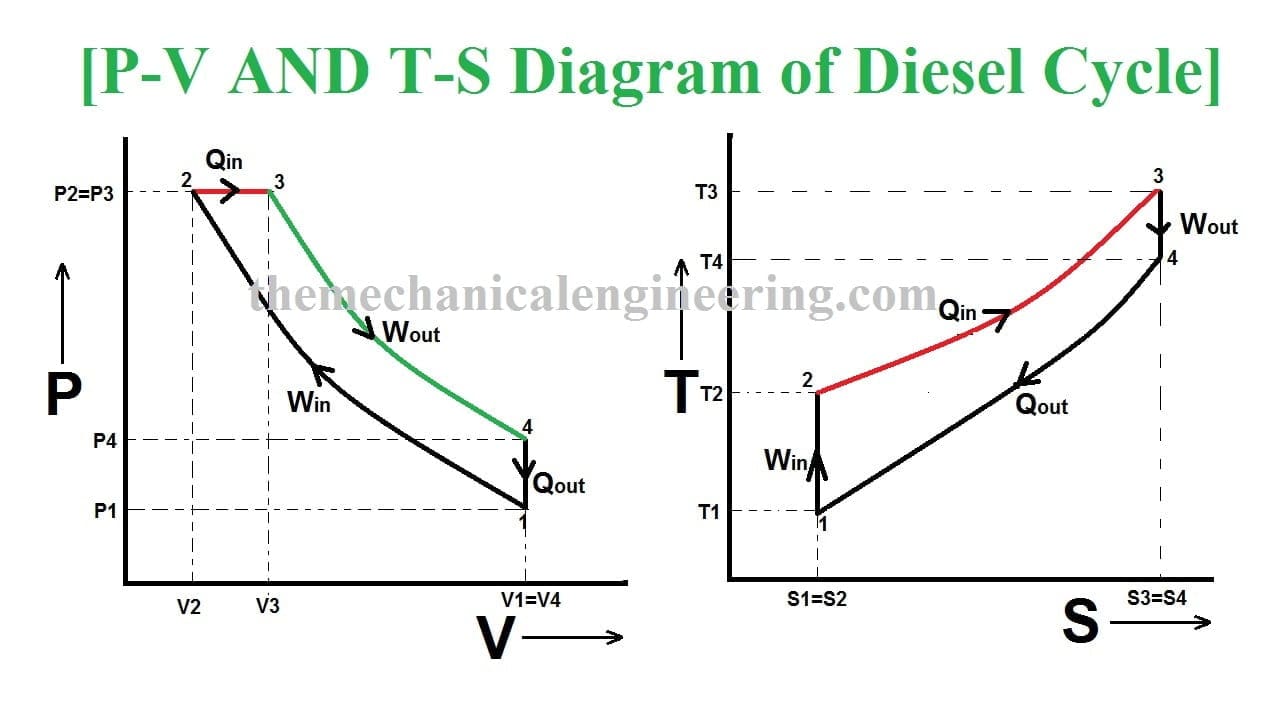
-
Process 1 → 2: Isentropic Compression
- This is identical to the Otto cycle. The piston moves from BDC (maximum volume,
V₁) to TDC (minimum volume,V₂), compressing the air. - Work is done on the gas. Pressure and temperature increase.
- The compression ratio (
r) is defined exactly the same way: .
- This is identical to the Otto cycle. The piston moves from BDC (maximum volume,
-
Process 2 → 3: Constant-Pressure Heat Addition
- This is the key difference. At state 2 (TDC), fuel injection begins. The combustion process pushes the piston outward, and the volume increases from
V₂toV₃. - We model this as heat (
Q_in) being added at constant pressure (P₂ = P₃). - This introduces a new, important parameter: the cutoff ratio (
r_c). It's the ratio of the volume at the end of heat addition ("fuel cutoff") to the volume at the start.
- Since volume is changing, work is being done by the gas during this process, in addition to heat being added.
- This is the key difference. At state 2 (TDC), fuel injection begins. The combustion process pushes the piston outward, and the volume increases from
-
Process 3 → 4: Isentropic Expansion (Power Stroke)
- This is the rest of the power stroke, from the point of fuel cutoff (
V₃) to BDC (V₄). - The hot, high-pressure gas continues to expand and push the piston, producing more work.
- This process is identical in nature to the Otto cycle's power stroke.
- This is the rest of the power stroke, from the point of fuel cutoff (
-
Process 4 → 1: Constant-Volume Heat Rejection
- This is also identical to the Otto cycle. At BDC (
V₄ = V₁), the cycle rejects waste heat (Q_out) to the surroundings, causing the pressure and temperature to drop back to the initial state.
- This is also identical to the Otto cycle. At BDC (
Let's quickly recap these four steps with another look at the diagrams.
Thermodynamics: Otto cycle, Diesel cycle (29 of 51)
This video walks through all four processes of the Diesel cycle on both the P-V and T-S diagrams, clearly labeling each state.
Watch the segment from 0:46:07 to 0:50:03, and then from 0:51:03 to 0:53:55. Follow along as the instructor draws and explains each of the four processes.
Test your understanding!
In the Otto cycle, the compression ratio r could be written as either or . Is this also true for the Diesel cycle? Why or why not?
Show answer
No, it is not true for the Diesel cycle.
In the Diesel cycle, heat is added at constant pressure while the volume increases from V₂ to V₃. This means V₃ is greater than V₂. Since V₄ = V₁, the ratio becomes . Because V₃ > V₂, the fraction is smaller than . Therefore, for a Diesel cycle, .
Calculating the Efficiency of the Diesel Cycle
Alright, let's get to the main event: deriving the efficiency. The game plan is the same as for the Otto cycle. We start with the fundamental definition of thermal efficiency:
Now, we need to find expressions for Q_in and Q_out using our cold-air-standard assumptions (air is an ideal gas with constant specific heats).
-
Heat Rejection (Process 4 → 1): This is a constant-volume process, so the heat rejected is related to the change in internal energy.
This is exactly the same as for the Otto cycle. -
Heat Addition (Process 2 → 3): This is a constant-pressure process. Remember from our First Law lessons that for a reversible constant-pressure process in a closed system, the heat transfer is equal to the change in enthalpy (
H).
This is where thec_pcomes in, instead of thec_vwe used for the Otto cycle!
Now, let's substitute these into the efficiency formula:
We can simplify this by recalling that the specific heat ratio is .
This is a correct formula, but just like with the Otto cycle, it's not very practical as it depends on all four temperatures. Our goal is to express it using only the compression ratio (r), the cutoff ratio (r_c), and the specific heat ratio (k).
This requires a bit of algebraic heavy lifting. Let's walk through it together.
The Goal: Eliminate T₁, T₂, T₃, T₄. We'll do this by expressing T₂, T₃, and T₄ in terms of T₁.
-
Find
T₂fromT₁: Process 1→2 is isentropic. -
Find
T₃fromT₂: Process 2→3 is constant pressure. For an ideal gas, . SincePis constant,V/Tmust be constant.
Substituting our expression forT₂: -
Find
T₄fromT₃: Process 3→4 is isentropic.
We need to figure out the volume ratio . We knowV₄ = V₁. Let's use our new ratios:
So, the expansion ratio for this part of the stroke isr/r_c.
Now substitute our expression forT₃:
Phew! Now we have all four temperatures in terms of T₁ and our ratios. Let's substitute them back into our efficiency equation:
T₁ is in every term, so it cancels out. Let's factor r^(k-1) from the denominator.
Rearranging this to look more like the Otto cycle formula gives us the final result:
Analyzing the Diesel Efficiency Formula
Take a close look at this formula.
- The first part, , is the exact formula for the Otto cycle efficiency!
- The second part, the term in the brackets, is a new factor that accounts for the constant pressure heat addition.
Since k > 1 and the cutoff ratio r_c is always greater than 1 (because volume increases), it can be shown that the bracketed term is always greater than 1.
This leads to a crucial insight: For the same compression ratio (r), the ideal Diesel cycle is less efficient than the ideal Otto cycle.
So why are real-world diesel engines usually more fuel-efficient than gasoline engines? The answer lies in the compression ratio. Because a diesel engine compresses only air, it isn't limited by engine knock. It can use much higher compression ratios (r ≈ 15-22) than a gasoline engine (r ≈ 8-12). The huge efficiency gain from this much higher r more than makes up for the penalty from the cutoff ratio term.
Worked Problem: Analyzing a Diesel Cycle
Let's put the theory into practice with a full analysis.
Problem Statement:
An ideal Diesel cycle has a compression ratio of 18 and a cutoff ratio of 2. At the beginning of the compression process (state 1), the air is at 100 kPa and 20°C. Using the cold-air-standard assumptions (air is an ideal gas with constant specific heats), determine:
a) The temperature and pressure at the end of each of the four processes.
b) The net work output per kilogram of air.
c) The thermal efficiency of the cycle.
For air, use kJ/kg·K, kJ/kg·K, and .
Step-by-Step Solution
First, let's list our knowns:
- kPa
- K (Remember to always use Kelvin!)
a) Find Temperature and Pressure at States 2, 3, and 4
-
State 2 (End of Isentropic Compression):
- (or 5.72 MPa)
-
State 3 (End of Constant-Pressure Heat Addition):
- This process is constant pressure, so .
- . This is the peak temperature.
-
State 4 (End of Isentropic Expansion):
- To find
P₄, we can use the ideal gas law between state 1 and state 4.V₁ = V₄.
Summary of States:
- State 1: 293.15 K, 100 kPa
- State 2: 931.3 K, 5720 kPa
- State 3: 1862.6 K, 5720 kPa
- State 4: 773.6 K, 264 kPa
b) Find Net Work Output (w_net)
w_net = q_in - q_out. Let's find the heat transfers.- Heat Input (2→3, constant pressure):
- Heat Output (4→1, constant volume):
- Net Work:
c) Find Thermal Efficiency (η_th)
- Let's use both methods to check our work.
- Method 1: Using heat transfers.
- Method 2: Using the efficiency formula.
- The results match perfectly (allowing for minor rounding differences). The thermal efficiency is 63.2%.
Conclusion
Fantastic work today! We've successfully dissected the Diesel cycle and contrasted it with the Otto cycle we learned previously. You now have the tools to analyze the two most important ideal cycles for internal combustion engines.
Key Takeaways:
- The Diesel cycle is the ideal model for compression-ignition engines.
- Its key feature is constant-pressure heat addition, which models the fuel injection process. This is different from the Otto cycle's constant-volume heat addition.
- Analyzing the Diesel cycle requires a new parameter: the cutoff ratio (
r_c), which measures how long the fuel injection process lasts. - The efficiency of an ideal Diesel cycle is given by the formula:
- For the same compression ratio, a Diesel cycle is less efficient than an Otto cycle. However, real diesel engines achieve higher overall efficiency by operating at much higher compression ratios.
Preview of the Next Lesson
We've now established that for the same compression ratio, Otto is more efficient, but in reality, Diesel engines often win on fuel economy. This begs for a more direct comparison. In our next lesson, we will do just that. We'll put the Otto and Diesel cycles side-by-side and compare their performance under different constraints, such as having the same peak pressure or the same heat input, to truly understand the pros and cons of each design.