Hello! Welcome back.
In our last session, we constructed the master key for analyzing systems with fluid flowing through them: the Steady-Flow Energy Equation (SFEE).
We saw this is just a detailed accounting statement for energy: energy in = energy out.
Today, we get to be detectives. We're going to take this universal equation and apply it to specific, real-world machines. A huge part of engineering is knowing what you can safely ignore. For some devices, work is zero. For others, kinetic energy changes are everything. Our job is to start with the full SFEE and cross out the terms that aren't important for the device we're studying. This simplifies the problem dramatically and reveals the core function of the machine.
Let's look at the "suspects" we'll be analyzing today:
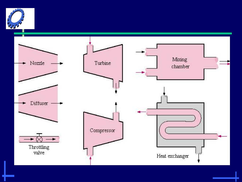
Our goal is to create a simplified, practical version of the SFEE for each of these four devices.
A General Approach to Analyzing Devices
Before we dive in, let's establish a consistent thought process for every device. We'll start with the full SFEE and ask a series of questions:
- Heat Transfer (): Is the device typically insulated? Does heat transfer happen, but it's tiny compared to other energy changes? If so, we can often assume it's adiabatic ().
- Work (): Does the device have moving parts designed to produce or consume power (like a spinning shaft)? If not, then .
- Potential Energy (): Is there a large change in elevation between the inlet and outlet? For most compact devices like nozzles or turbines, this change is negligible ().
- Kinetic Energy (): Is changing the fluid's speed the primary purpose of the device? Or are the velocities at the inlet and outlet slow and/or similar? This will determine if the terms are important.
Let's put this process into action.
Nozzles and Diffusers: The Velocity Changers
First up are nozzles and diffusers. These are the simplest devices because they have no moving parts.
- A Nozzle is a device designed to increase a fluid's velocity. Think of the nozzle on a garden hose or a fire hose. You trade pressure for speed.
- A Diffuser is the exact opposite. It's designed to decrease a fluid's velocity, which in turn increases its pressure. The cone-shaped inlet of a jet engine is a diffuser; it slows down the incoming high-speed air before it enters the compressor.
To see how we simplify the SFEE for these devices, let's watch a short video segment.
Thermodynamics - 5-3 Energy analysis of steady flow devices
This video provides a clear walkthrough of the common assumptions made for steady-flow devices. Pay close attention to the reasoning for simplifying the SFEE for nozzles and diffusers.
Please watch the segment from 9:44 to 13:05. The presenter will start with the full SFEE for a single-inlet, single-outlet device and then cross out the terms that are typically negligible for nozzles and diffusers, explaining why.
As the video explained, here's our detective work for a nozzle or a diffuser:
- : There are no moving shafts to do work.
- : They are usually short and oriented horizontally.
- : The fluid passes through so quickly that there isn't much time for significant heat to transfer in or out. So we assume it's adiabatic.
Let's take our full SFEE and cross out these terms:
The mass flow rate is constant, so we can divide it out:
This elegant equation tells us the whole story. It's an energy trade-off!
- For a nozzle: The goal is to make much larger than . To do that, the fluid's enthalpy must decrease (). The fluid sacrifices its enthalpy to gain kinetic energy.
- For a diffuser: The goal is to make smaller than . This means the fluid's enthalpy must increase (). The fluid sacrifices its kinetic energy to gain enthalpy (which usually appears as a rise in pressure and temperature).
Test your understanding!
Imagine you put your hand in front of the nozzle of a can of compressed air. It feels very cold. Based on our simplified equation for a nozzle, can you explain why?
Show answer
The nozzle's job is to dramatically increase the air's velocity (). According to the equation , this huge increase in kinetic energy has to come from somewhere. It comes from the air's enthalpy. The enthalpy at the exit () drops significantly. For a gas, enthalpy is strongly related to temperature, so a big drop in enthalpy means a big drop in temperature, which is why the spray feels so cold.
Worked Numerical Problems: Nozzles & Diffusers
Let's run some numbers. For a deeper dive into the problem-solving process for these devices, you can refer to the resource "Steady Flow Systems - Nozzles and Diffusers" (LINK). The examples shown there are excellent. Here are a couple of problems for us to solve.
Problem 1: Air Nozzle
Air enters a nozzle at 200 kPa and 150°C with a very low velocity that we can neglect (). It exits the nozzle at a pressure of 100 kPa and a temperature of 100°C. What is the exit velocity of the air? (For air, we can use kJ/kg·K, and remember that for an ideal gas, ).
Show step-by-step solution
Step 1: Start with the simplified SFEE for a nozzle.
Step 2: Rearrange to solve for the exit velocity, .
Since , the equation becomes .
Rearranging gives:
Step 3: Relate the enthalpy change to temperature change for an ideal gas.
We know , so .
Our equation becomes:
Step 4: Plug in the values and check units!
- kJ/kg·K = 1005 J/kg·K (CRITICAL: We must use Joules to get m/s!)
- K
- K
- K (or 50°C, the difference is the same)
Remember that 1 J/kg = 1 m²/s².
The air accelerates to an impressive 317 m/s by dropping its temperature by 50°C.
Problem 2: Steam Diffuser
Steam enters a diffuser at a pressure of 80 kPa with a velocity of 300 m/s. It leaves as saturated vapor at 90 kPa with a very low velocity (). The diffuser is adiabatic. What was the state of the steam at the inlet (specifically, its quality)? (We will need steam tables for this).
Inlet (1): P₁=80 kPa, V₁=300 m/s
Outlet (2): P₂=90 kPa, saturated vapor, V₂≈0
Show step-by-step solution
Step 1: Start with the simplified SFEE for a diffuser.
Step 2: Find the exit enthalpy, .
The steam at the exit is saturated vapor at 90 kPa. We look this up in a steam table.
At kPa, the enthalpy of saturated vapor is kJ/kg.
Step 3: Rearrange the equation to solve for the inlet enthalpy, .
Since :
Step 4: Calculate and watch the units.
- kJ/kg
- m/s
The kinetic energy term is:
To subtract this from enthalpy, we must convert it to kJ/kg:
Now we can find :
Step 5: Determine the inlet quality, .
We know the inlet pressure kPa and we just found the inlet enthalpy kJ/kg. Now we go back to the steam tables at 80 kPa to see what state this is.
At kPa:
- Enthalpy of saturated liquid, kJ/kg
- Enthalpy of saturated vapor, kJ/kg
Since our (2623.1) is between and , the steam at the inlet was a saturated liquid-vapor mixture. We can find the quality () using the formula:
The inlet steam was a mixture with a quality of 98.2% (i.e., it was 98.2% vapor by mass).
Turbines and Compressors: The Work Machines
Next, we look at devices whose entire purpose is to interact with work.
- A Turbine is a device that produces work by letting a high-energy fluid expand and push on a set of blades. Think of a windmill, a hydroelectric dam, or the massive turbines in a power plant spun by high-pressure steam.
- A Compressor (or pump) is the opposite: it consumes work to increase the pressure of a fluid. A bicycle pump is a simple compressor; a jet engine's front section uses a powerful compressor to pressurize air before combustion.
This image clearly shows the difference in energy flow:
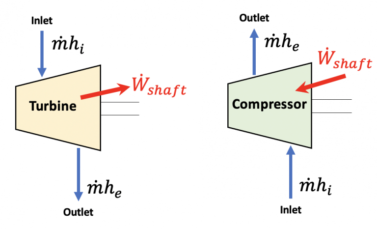
Now let's apply our detective skills to simplify the SFEE for these workhorses.
Thermodynamics - 5-3 Energy analysis of steady flow devices
Let's return to our video guide to see the analysis for turbines and compressors. Note how the assumptions differ from those for nozzles.
Please watch the segment from 13:05 to 16:01. The key takeaway here is which terms become dominant when work is involved.
Here's the summary of our analysis for turbines and compressors:
- : This is the most important term! It's the whole point of the device.
- : Again, typically negligible change in height.
- : For an ideal analysis, we assume they are perfectly insulated (adiabatic). In reality, turbines lose some heat and compressors get hot, but adiabatic is our baseline for calculating ideal performance.
- : While the fluid is moving, the inlet and outlet pipes are often designed such that the velocities are not drastically different. More importantly, the change in enthalpy is usually so enormous that the change in kinetic energy is like a drop in the bucket. We can often neglect it.
Let's simplify the SFEE with these assumptions:
Rearranging this gives us our final forms:
For a Turbine (Work Out):
This beautifully simple equation says: The power you get out of a turbine is equal to the mass flow rate times the drop in enthalpy of the fluid. The fluid gives up its energy to do work.
For a Compressor (Work In):
This says: The power you must put into a compressor is equal to the mass flow rate times the rise in enthalpy of the fluid. You are doing work to pump energy into the fluid.
Worked Numerical Problems: Turbines & Compressors
The provided textbook chapter, "THE FIRST LAW APPLIED TO STEADY FLOW ..." (LINK), is a fantastic resource with many worked examples for these devices. Let's tackle a couple.
Problem 3: Steam Turbine Power
A steam turbine in a power plant receives steam at a rate of 50 kg/s. The inlet conditions are 70 bar and 500°C. The steam leaves the turbine at 0.08 bar with a quality of 90% (x=0.9). Assuming the process is adiabatic, what is the power output of the turbine in Megawatts (MW)?
Show step-by-step solution
Step 1: Start with the simplified SFEE for a turbine.
Step 2: Find the inlet enthalpy, .
We look in the superheated steam tables for bar and °C.
From the tables, kJ/kg.
Step 3: Find the exit enthalpy, .
The exit is a saturated mixture at bar with quality . We need and at 0.08 bar from the saturated steam tables.
- kJ/kg
- kJ/kg
Now use the quality formula:
Step 4: Calculate the power output.
- kg/s
- kJ/kg
- kJ/kg
Since 1 MW = 1000 kW, the power output is 53.7 MW. That's enough to power tens of thousands of homes, all from the enthalpy drop of steam!
Problem 4: Air Compressor Power
An adiabatic compressor takes in air at 100 kPa and 300 K and compresses it to 800 kPa. The air exits at a temperature of 540 K. The mass flow rate is 2 kg/s. What is the power input required to run the compressor? (Again, for air, kJ/kg·K and ).
Show step-by-step solution
Step 1: Start with the simplified SFEE for a compressor.
Step 2: Relate enthalpy change to temperature change.
Step 3: Plug in the values.
- kg/s
- kJ/kg·K
- K
- K
The compressor requires 482.4 kW of power to run. This energy is transferred into the air, increasing its temperature and pressure.
Conclusion
Fantastic work today. We've taken our master equation and learned how to apply it like a true engineer—by simplifying it to fit the problem at hand.
Key Takeaways:
- The SFEE is our starting point for all steady-flow devices.
- Nozzles & Diffusers are work-free devices that trade enthalpy for kinetic energy. Their simplified equation is: .
- Turbines & Compressors are devices where work is the main event. We usually neglect kinetic and potential energy changes.
- Turbine Power Out:
- Compressor Power In:
- The art of thermodynamic analysis is knowing which terms matter and which are just "noise" for a given device.
Preview of the Next Lesson
We've covered devices that change velocity and devices that do work. But what about devices whose primary purpose is to handle heat or simply drop pressure?
In our next lesson, we will continue our investigation by analyzing two more crucial components:
- Throttling Devices (like valves): These cause a large pressure drop with almost no change in enthalpy. We'll see why they are essential in refrigeration.
- Heat Exchangers: These are devices designed to transfer heat between two fluid streams without letting them mix. They are the heart of power plants and air conditioners.
We'll see how the SFEE simplifies in completely different ways to describe these essential pieces of equipment.