Introduction
Welcome back! In our previous lesson, we established a strong theoretical foundation by exploring the QEMU Object Model (QOM). You learned how QOM uses C structs and function pointers to create a powerful object-oriented framework for representing devices, managing their lifecycles (instance_init vs. realize), and enabling modularity within QEMU.
Now, it's time to put that theory into practice. This lesson is designed to be highly hands-on, directly addressing the learning outcome: Implement a simple emulated memory-mapped (MMIO) device in QEMU and make it accessible to a guest. We will walk through the entire process, from writing the C code for a device to compiling it into QEMU and seeing it appear in a running guest operating system. This is a fundamental skill for anyone looking to contribute to QEMU or understand virtualization at a deep level.
1. Conceptual Framework: MMIO in QEMU
Before we dive into the code, let's quickly solidify our mental model of how a Memory-Mapped I/O (MMIO) device works within QEMU.
When a guest operating system wants to communicate with a hardware device, it reads from or writes to specific physical memory addresses. These addresses are not mapped to RAM but are reserved for the device.
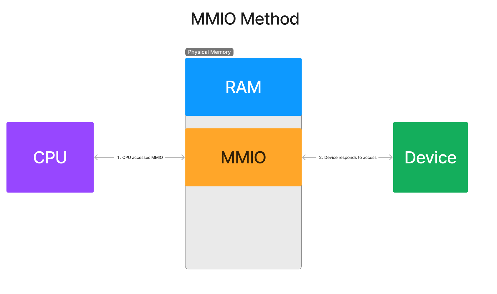
QEMU emulates this process beautifully. The emulated CPU executes the guest's load/store instruction. QEMU's virtual Memory Management Unit (MMU) intercepts the access, recognizes that the address falls within a range registered by an emulated device, and instead of accessing memory, it calls a C function within your device model.
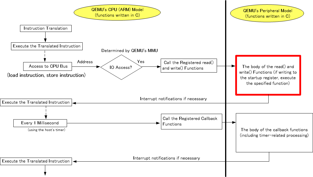
Our task today is to implement the "QEMU Peripheral Model" box for a new, custom device.
2. Implementing a PCI MMIO Device
For our practical example, we will implement a simple PCI device. While the PCI protocol has its own complexities (which we will explore in a later module), it provides a very convenient way to work with MMIO regions via its Base Address Registers (BARs). We will create a device, attach it to the emulated PCI bus, and access its registers from the guest.
We will follow an excellent video guide that walks through creating a "PCI Echo" device. I will break down the process and connect each step back to the QOM concepts we've learned.
Implement a custome QEMU PCI Device
First, let's get an overview of the device we're about to build. This video, 'Implement a custom QEMU PCI Device' by Johannes 4GNU_Linux, will be our primary guide. Watch this first segment to understand the device's specification.
Watch from the beginning to 02:27. Focus on the description of the device's two BARs: BAR0: A 16-byte region with several 4-byte control registers (ID, invert, IRQ, random value). BAR1: A 4KB region that acts as a simple storage buffer (an 'echo' buffer). \nThis specification defines the requirements for our implementation.
Step 1: Device State and MMIO Callbacks
The first step in creating any QOM device is to define its state and its core I/O logic.
- State Struct: This C struct will hold all the runtime data for our device. For the PCI Echo device, this includes storage for its registers and the 4KB echo buffer.
- Read/Write Callbacks: These are the C functions that QEMU will call for any guest access to our device's MMIO regions. They receive the offset within the region being accessed, the value being written (for write operations), and the access size. Your code is responsible for emulating the correct behavior based on these parameters.
Implement a custome QEMU PCI Device
Now, let's see how the state and MMIO callbacks are implemented. This part of the video shows the C code for handling read and write accesses to both BAR0 and BAR1.
Watch from 02:27 to 06:56. Pay close attention to: The PCIEchoDevice struct: This is the device's main state structure. The memory_region_operations struct: This is where the function pointers for read and write are defined. The pci_echo_bar0_read/write functions: Note how a switch statement on the address (hwaddr) is used to differentiate between the registers within BAR0. The pci_echo_bar1_read/write functions: Notice the careful handling of different access sizes (1, 2, 4, and 8 bytes) using pointer casting. This is a common and important pattern in low-level driver and emulator development.
Step 2: QOM Lifecycle and Type Registration
With the core logic defined, we need to wrap it in the QOM framework. This involves telling QEMU about our new device type and implementing the key lifecycle functions (realize, class_init) that we discussed in the last lesson.
class_init: This function is called once per class. It's the perfect place to set static properties of the device, such as its PCI Vendor ID and Device ID.realize: This function is called once per instance when the device is being activated. Here, we'll initialize our memory regions and register them with the PCI subsystem as BARs.TypeInfo: This static struct is the final piece that registers our newpci-echo-devicetype with QEMU's type system, linking it to a parent type (TYPE_PCI_DEVICE) and pointing to our lifecycle functions.
Implement a custome QEMU PCI Device
Let's see how these QOM lifecycle functions are used to bring the device to life.
Watch from 06:56 to 09:23. Observe how the concepts from our last lesson map directly to this code: In the realize function, memory_region_init_io is called to link our MMIO operation callbacks to a memory region, and pci_register_bar makes that region available to the guest as a PCI BAR. In the class_init function, the PCI configuration space is initialized with the vendor ID (0x1234) and device ID (0xBEEF). The video points out the type_init macro at the end, which is how the device registers itself with QEMU's object model.
If you want to see another clear, well-commented example of this structure for a simpler, non-PCI device, the "banana_rom" walkthrough is an excellent reference.
Writing a custom device for QEMU
For an alternative perspective, this blog post by Sebastien Bourdelin implements a simple ROM device for the system bus. It provides a very clean illustration of the core QOM structures.
Skim through the sections 'The QEMU Object Model (QOM)' and 'Device file operations'. Compare the TypeInfo, BananaRomState, banana_rom_instance_init, and banana_rom_ops structures to what you saw in the video. You'll see the same fundamental QOM patterns at play.
3. Integration and Compilation
You've written the C code, but QEMU doesn't know about your new file yet. You must integrate it into QEMU's build system. This typically involves modifying meson.build files to conditionally compile your source file based on a configuration option.
Implement a custome QEMU PCI Device
This next segment shows the necessary modifications to QEMU's build configuration files.
Watch from 09:23 to 10:21. The video demonstrates editing two files: hw/misc/Kconfig (or a similar config file) to define a new build option for the device. hw/misc/meson.build to instruct the build system to compile your .c file when that option is enabled. \nAfter making these changes, you must re-run QEMU's ./configure script and then re-compile with make.
4. Running the Guest and Testing the Device
This is the moment of truth. After successfully compiling QEMU with your new device, you can now instantiate it in a virtual machine and see if the guest OS can detect it.
- Instantiation: We use the
-devicecommand-line argument to tell QEMU to create an instance of ourpci-echo-device. - Verification: Once the guest Linux system boots, we can use the
lspcicommand. This utility scans the PCI bus and lists all detected devices. If everything worked, our device should appear with the Vendor and Device IDs we set inclass_init.
Implement a custome QEMU PCI Device
Let's watch the final part of the video to see the device in action.
Watch from 10:21 to the end (13:44). Pay attention to: The full QEMU launch command, especially the -device pci-echo-device argument. The kernel boot messages, where you can see the PCI bus being scanned and a device with ID 1234:beef being discovered. The final verification using lspci within the guest, which confirms our device is present and correctly identified.
Congratulations! By following these steps, you have successfully implemented a new MMIO device, integrated it into QEMU, and made it accessible to a guest.
Interview Scenario
An interviewer presents you with the following situation:
"You've written a new MMIO device in QEMU. When the guest OS writes the value 0xABCD to your device's control register at offset 0x04, you expect an internal state flag in your device's C struct to be set. However, when you inspect the state with GDB, the flag remains unset. The guest driver appears to be writing to the correct physical address. What are the first three places you would look in your QEMU device C file to debug this?"
Click to see a model response
Here is a structured approach to debugging this issue:
-
Check the Write Callback (
_writefunction): This is the entry point for the MMIO access. I would start here.- Action: Add a
qemu_logstatement (or use a GDB breakpoint) at the very beginning of the write callback function. I'd print thehwaddr(offset),val(value), andsizeof the access. - Purpose: This immediately confirms if QEMU is dispatching the write to my function at all, and if the offset and value are what I expect (
hwaddr=0x04,val=0xABCD). If this log doesn't appear, the problem is higher up (e.g., in the memory region registration inrealize).
- Action: Add a
-
Verify the Register-Decoding Logic: Assuming the write callback is being hit correctly, the next most likely culprit is the logic that interprets the offset.
- Action: I would examine the
switch (hwaddr)statement orif/elsechain inside the write callback. - Purpose: I'm looking for common errors: Is there a typo in the macro for the register's offset (e.g.,
REG_CONTROLis defined as0x8instead of0x4)? Is there a missingbreak;in theswitchstatement, causing a fallthrough to another case? Is the logic for handling the accesssizecorrect?
- Action: I would examine the
-
Inspect the State-Update Code: If the correct code block for offset
0x04is being executed, the final place to look is the line of code that actually modifies the state.- Action: I would look at the C statement that sets the flag (e.g.,
s->control_flag = 1;wheresis the pointer to the device's state struct). - Purpose: Is there a logic error here? Am I accidentally modifying a different variable? Is there a bitmask being applied incorrectly (e.g.,
s->regs[0] |= FLAGwhen it should be a direct assignment)? Placing a GDB breakpoint right after this line and inspecting thesstruct would definitively show whether the state was updated as intended.
- Action: I would look at the C statement that sets the flag (e.g.,
By systematically checking these three areas—entry point, decoding logic, and state update—I can efficiently pinpoint the source of the bug within the device model itself.
Conclusion
In this lesson, we bridged the gap between theory and practice. You have seen how the abstract concepts of the QEMU Object Model—types, classes, state objects, and lifecycle functions—come together to create a tangible, working emulated device.
Key Takeaways:
- Implementing an MMIO device involves creating a state struct, defining read/write callbacks in a
MemoryRegionOpsstruct, and handling accesses based on offset and size. - The QOM lifecycle is essential:
class_initsets class-wide data (like PCI IDs), whilerealizeactivates the device by initializing and registering resources like MMIO regions. - Integrating a new device requires modifying QEMU's build system (
meson.build) to include your source file. - Testing involves launching QEMU with the
-deviceflag and using guest-side tools (likelspciordevmem) to verify the device's presence and functionality.
Preview of the Next Lesson:
We have now emulated a simple, self-contained piece of hardware. However, many modern devices use a more efficient communication method than simple MMIO polling, especially for high-throughput I/O. In the next lesson, we will explore this advanced mechanism as we describe the virtio transport mechanism, including virtqueues and the guest-to-host notification pathway. This will introduce you to paravirtualization, a cornerstone of high-performance virtualization in KVM and QEMU.