Introduction
In our previous lesson, we established the high-level architecture of QEMU, distinguishing its role as a pure emulator using the Tiny Code Generator (TCG) from its role as a virtual machine monitor (VMM) leveraging the KVM accelerator. You learned that when a guest performs an I/O operation that KVM cannot handle directly, it triggers a VM exit, and KVM passes control back to the QEMU userspace process to perform device emulation.
This lesson dives into the specifics of that process. Our goal is to explain the mechanisms of hardware device emulation in QEMU, including Memory-Mapped I/O (MMIO), Port-Mapped I/O (PIO), and interrupt injection. Your background in embedded systems will be invaluable here, as the concepts of device registers and interrupts are central to both physical hardware and its software emulation. We will explore how QEMU essentially creates a software-defined "datasheet" for virtual hardware that the guest OS can interact with.
1. How a CPU Communicates with Physical Devices
Before we can understand emulation, we must first solidify our understanding of what is being emulated. In the physical world, CPUs don't micromanage every aspect of a peripheral like a hard drive or network card. Instead, they communicate with a dedicated device controller. This interaction follows well-defined protocols.
Let's watch a video that provides an excellent conceptual overview of how CPUs interact with I/O devices.
How CPUs Interact with So Many Different Devices
The video 'How CPUs Interact with So Many Different Devices' from the Core Dumped channel clearly explains the fundamental concepts of device communication.
Please watch the following segments: Device Controllers (01:02 - 06:53): Focus on why CPUs communicate with controllers rather than controlling devices directly. This establishes the abstraction layer that QEMU emulates. MMIO (08:56 - 10:32): Pay close attention to how device registers are mapped into the CPU's physical address space. This is the most common I/O method in modern systems. PIO (10:41 - 12:10): Understand this as an alternative, x86-specific mechanism that uses a separate I/O address space and special instructions. Polling vs. Interrupts (12:18 - 14:02): Grasp the difference between the CPU repeatedly checking a device's status (polling) and the device actively signaling the CPU when it's ready (interrupts). This contrast motivates the need for interrupt emulation.
To summarize the key points from the video:
- Memory-Mapped I/O (MMIO): A region of the physical address space is reserved not for RAM, but for a device's registers. The CPU uses standard
loadandstore(e.g.,MOVin x86) instructions to communicate with the device, treating its registers like variables in memory. This is the dominant method used in ARM architectures and for most modern devices on x86 (like those on the PCIe bus). - Port-Mapped I/O (PIO) or Isolated I/O: A separate, smaller address space (called "I/O ports") is used for devices. The CPU needs special instructions (e.g.,
inandouton x86) to access this space. This is largely a legacy mechanism on x86, used for older peripherals like PS/2 keyboards and serial ports. - Interrupts: A hardware mechanism for a device to signal the CPU, causing it to pause its current work and execute a specific piece of code called an Interrupt Service Routine (ISR). This is far more efficient than polling.
With these physical concepts in mind, let's see how QEMU recreates them in software.
2. Emulating I/O Access in QEMU
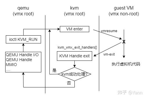
When a guest OS wants to talk to a device, it performs either an MMIO or a PIO operation. In a KVM-accelerated environment, both of these actions will cause a VM exit.
Emulating Memory-Mapped I/O (MMIO)
This is the core of modern device emulation. The process relies on QEMU's MemoryRegion API.
- Registration: During QEMU's initialization, the C code for an emulated device creates a
MemoryRegionobject. This object is associated with a set of callback functions (e.g.,my_device_readandmy_device_write). QEMU then maps this region to a specific range in the guest's physical address space. - Guest Access & VM Exit: The guest driver writes to a memory address within this mapped range. Because this memory range is not backed by actual RAM, the access causes an EPT (Extended Page Table) violation, triggering a VM exit to KVM.
- KVM to QEMU: KVM analyzes the exit reason, identifies it as an MMIO access, and returns from the
KVM_RUNioctlcall back to the QEMU vCPU thread. KVM provides QEMU with all the details: the physical address, the data written, and the access size (byte, word, etc.). - Dispatch to Device Model: QEMU's memory subsystem looks up which
MemoryRegioncorresponds to the accessed address and calls the appropriate registered C function (e.g.,my_device_write), passing it the data from the guest. - Emulation: The C function now executes, simulating the behavior of the real hardware. For example, if the guest wrote to a "transmit" register on a virtual network card, this C function might take the packet data and send it to the host's network stack via a TAP device.
The following article provides a fantastic, practical walkthrough of creating a simple MMIO device in QEMU. It will make these steps concrete.
Building a Virtual Hardware Device from Scratch using MMIO in QEMU
The article 'Building a Virtual Hardware Device from Scratch using MMIO in QEMU' by Ahmed Dajani is an excellent resource. It explains the core concepts and shows a complete example.
Please read from the beginning down to the section 'Talking to the Device from Userspace'. Focus on these key parts: 'What is MMIO?': Reinforces the concept of memory-mapped registers. 'MMIO Is Everywhere': These real-world examples (APIC, UART, NVMe) will be familiar from your embedded background and demonstrate the ubiquity of this pattern. 'How QEMU Models the System Bus': This explains the MemoryRegion infrastructure and the critical role of read/write callbacks. 'A Toy Example': Skim the code to see how a device's state, register map, and callbacks are implemented in a C struct. 'Wiring Into the... Machine': Understand that an emulated device must be explicitly instantiated and mapped into the guest's address space during machine initialization.
Emulating Port-Mapped I/O (PIO)
Emulating PIO is conceptually similar but is triggered differently.
- Guest Access & VM Exit: The guest executes an
inoroutinstruction. Since these are privileged, they always cause a VM exit. - KVM to QEMU: KVM's exit handler identifies the cause as an I/O instruction. It passes the port number, data (for
out), and direction back to QEMU. - Dispatch and Emulation: QEMU has a separate I/O port dispatch mechanism. It looks up the handler registered for that port number and calls it. The C function then emulates the device behavior, just like in the MMIO case.
While architecturally important for x86 emulation, most modern device development in QEMU focuses on MMIO, as it's the standard for PCIe and most SoC peripherals.
3. Signaling the Guest: Interrupt Injection
After QEMU emulates a device action, it often needs to notify the guest that the operation is complete or that an external event has occurred (e.g., a packet has arrived). This is done by injecting a virtual interrupt.
QEMU cannot simply write to the guest's memory to simulate an interrupt. It must ask the hypervisor (KVM) to do it.
The process is as follows:
- Device Emulation Completes: The C code for the emulated device decides an interrupt is needed. For example, a virtual timer has expired.
- QEMU Requests Injection: The device model code calls an internal QEMU function (e.g.,
qemu_set_irq()). This ultimately results in anioctlcall to KVM, often through a mechanism calledirqfd. Anirqfdis a file descriptor that QEMU can write to, which signals KVM to trigger a specific interrupt line in the guest. - KVM Delivers the Interrupt: KVM receives the signal from QEMU. On the next VM entry, or by momentarily interrupting the guest, KVM configures the virtual CPU state to indicate a pending interrupt.
- Guest Handles the Interrupt: From the guest's perspective, a hardware interrupt has occurred. The guest CPU automatically transfers control to the appropriate Interrupt Service Routine (ISR) that the guest OS registered for that device, completing the cycle.
The following resource, while focused on vhost, has an excellent section describing the data and interrupt path for a "Pure VirtIO" device, which is a device emulated entirely by QEMU.
Introduction to VirtIO, Part 2: Vhost
The blog post 'Introduction to VirtIO, Part 2: Vhost' provides very clear diagrams and explanations of the I/O and interrupt flow in a standard QEMU/KVM setup. We will focus only on the 'Pure VirtIO' parts, which describe QEMU's role as the device emulator.
Please read the following two sections: 'Limitations of Pure VirtIO': Study the text and Figure 2. The transmit path (steps 1b, 2a, 2b) shows the guest kick (an MMIO write causing a VM exit), and the receive path (steps 2c, 3) clearly shows QEMU using a syscall to KVM to request an interrupt injection. 'Terms & Definitions': Review the definitions for KVM, Doorbell Register, irqfd, Interrupts, and VM Exit / Entry. This will solidify your vocabulary.
4. A Real-World Case Study: Emulating a Smartphone GPU
To see how these mechanisms come together, let's look at a presentation about emulating a complex, real-world device: a Qualcomm GPU.
39C3 - Build a Fake Phone, Find Real Bugs: Qualcomm GPU Emulation and Fuzzing with LibAFL QEMU
The talk 'Build a Fake Phone, Find Real Bugs' shows the practical application of the concepts we've discussed. The speaker emulates parts of a Snapdragon SoC to fuzz the GPU driver.
Watch these two segments: Device Tree and MMIO (11:37 - 15:08): Notice how the speaker uses the device tree (DTB) to understand the hardware layout, specifically the MMIO ranges for different devices. This is the starting point for any device emulation project. Emulating Devices and Interrupts (24:03 - 27:13): The speaker describes emulating several small helper devices (PMIC, SMMU, HFI). Listen for how they mention asynchronous communication using interrupts (FMC protocol) and DMA, which are all orchestrated using the MMIO and interrupt injection mechanisms we've covered.
This case study demonstrates that emulating a complex system involves creating multiple, interacting device models, each with its own MMIO registers and interrupt lines, all working together to present a cohesive hardware platform to the guest kernel.
Interview Scenario
An interviewer presents you with the following task:
"A guest's network driver needs to transmit a packet. To do this, it writes the address of a packet descriptor to a 'transmit' register on an emulated NIC. Walk me through the entire lifecycle of this operation, from the guest's perspective to QEMU's and back."
Here is a model response:
-
Guest Action (MMIO Write): The guest driver executes a store instruction (e.g.,
mov [0xFE000000], eax) to write the descriptor address to the NIC's transmit register. This address,0xFE000000, is in a Memory-Mapped I/O (MMIO) region. -
VM Exit: Because this address is mapped as an MMIO region and not as normal RAM, the memory access causes a trap. The CPU hardware exits "guest mode" and transfers control to the KVM kernel module. This is a VM exit.
-
KVM to QEMU: KVM inspects the exit reason and determines it's for an I/O operation that needs to be handled in userspace. The
ioctl(KVM_RUN)call returns to the QEMU process, passing information about the MMIO access: the address, the data written, and the size of the write. -
QEMU Device Dispatch: QEMU's memory subsystem receives this request. It looks up its table of registered
MemoryRegions and finds that0xFE000000belongs to the emulated NIC device. It then invokes thewritecallback function for that device model. -
Device Emulation: The NIC's C
writefunction executes. It reads the descriptor from the guest's emulated RAM (which is just memory within the QEMU process), and simulates the packet transmission, likely by writing the packet data to a host-sidetapnetwork interface. -
Interrupt Request: After successfully processing the packet, the emulated NIC needs to inform the guest driver that the transmission is complete. The device model code requests an interrupt by calling an internal QEMU function, which typically writes to an
irqfdfile descriptor shared with KVM. -
Interrupt Injection: KVM is notified via the
irqfdand injects a virtual interrupt into the vCPU on the next VM entry. -
Guest ISR: The guest CPU receives the interrupt, saves its state, and jumps to the network driver's registered Interrupt Service Routine (ISR). The ISR would then typically read a status register on the NIC (another MMIO read, repeating the cycle) to confirm completion and clean up the descriptor.
Conclusion
In this lesson, we deconstructed the magic behind QEMU's hardware emulation. You've learned that it's a well-defined process built on the same concepts that govern physical hardware, simply translated into a software domain managed by QEMU and KVM.
Key Takeaways:
- Device emulation hinges on trapping guest I/O operations and dispatching them to handler functions in QEMU.
- MMIO is the primary mechanism, where guest memory accesses to specific physical addresses trigger a VM exit and are routed to C callbacks via QEMU's
MemoryRegioninfrastructure. - PIO is a legacy x86 mechanism handled similarly, but triggered by special
in/outinstructions. - Interrupt Injection is the reverse path: QEMU requests that KVM deliver a virtual interrupt to the guest to signal event completion, allowing for efficient, asynchronous device operation.
Preview of the Next Lesson:
Now that you understand the mechanisms of device emulation, you're ready to learn about the framework QEMU provides for organizing them. In the next lesson, we will explore the QEMU Object Model (QOM). You'll learn how QOM provides a structured, object-oriented system for defining device properties, managing their lifecycle, and connecting them to buses, which is the final prerequisite before you can implement your own simple device.