Introduction
In our last lesson, we explored the voltage divider and uncovered a critical limitation: the "loading effect," where connecting a component to the output causes the voltage to drop. We saw that this happens because the load draws current, changing the dynamics of the circuit. While we could calculate this effect for a simple voltage divider, what about more complex circuits? Re-analyzing an entire network every time a load changes is inefficient and cumbersome.
This lesson introduces a powerful tool for abstraction in circuit analysis: Thévenin's Theorem. It provides a systematic way to address the loading effect for any linear circuit. You'll learn how to take a complex network of sources and resistors and replace it with a simple, functionally identical equivalent: a single voltage source in series with a single resistor. From the perspective of a load, this simplified circuit is indistinguishable from the original. This process is akin to creating a clean interface or API for a complex software module, allowing you to understand its external behavior without needing to know the internal implementation details—a concept that should feel familiar from your software engineering background.
Why We Need an Equivalent Circuit
Imagine you're designing a system where you need to test how different sensor modules (the "load") behave when connected to your main circuit. As we saw with the voltage divider, each time you swap the load resistor , the overall circuit's properties change, forcing a complete re-analysis. This is tedious and impractical.
Thévenin's theorem offers a brilliant solution. It allows us to characterize the rest of the circuit—everything except the load—by asking: "From the load's perspective, what does this circuit look like?" The answer is always the same: it looks like an ideal voltage source () with a single resistor in series (). Once you find these two values, you can analyze the load's behavior for any by solving a simple series circuit, dramatically simplifying your work.
DC Thevenins Theorem (OLD LECTURE)
The introduction to this lecture by Jim Pytel effectively frames the problem that Thévenin's theorem solves.
Watch the segment from electrical loads. The presenter highlights the frustration of repeatedly re-analyzing a circuit for different load values, motivating the need for a simpler equivalent model.
The Thévenin Equivalent Circuit
Thévenin's theorem states that any linear two-terminal circuit can be replaced by an equivalent circuit consisting of a single voltage source, , in series with a single resistor, .
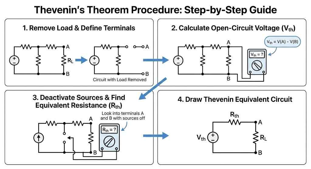
To create this equivalent circuit, we need to find two values: the Thévenin Voltage () and the Thévenin Resistance (). The process is a systematic, two-step procedure.
Step 1: Finding the Thévenin Voltage ()
The Thévenin voltage is the open-circuit voltage at the terminals where the load is connected.
Procedure:
- Remove the load resistor from the circuit, leaving the terminals (let's call them A and B) open.
- Calculate the voltage across these open terminals, . This voltage is your Thévenin voltage, .
Because no current can flow out of the open terminals, this calculation is often simpler than analyzing the original, fully connected circuit. You can use any of your known analysis techniques, like Ohm's Law, KVL, or the voltage divider rule.
DC Thevenins Theorem (OLD LECTURE)
This segment of Jim Pytel's lecture provides a clear explanation and example of finding the Thévenin voltage.
Watch the section explaining the procedure for finding Eth (the video uses 'Eth' for Thévenin voltage). Pay close attention to how removing the load simplifies the circuit into a basic series circuit, allowing the use of the voltage divider rule.
Step 2: Finding the Thévenin Resistance ()
The Thévenin resistance is the equivalent resistance of the circuit "looking back" into the terminals where the load was connected, with all independent sources deactivated.
Procedure:
- Remove the load resistor (if you haven't already).
- Deactivate all independent sources:
- Voltage sources are replaced with short circuits (a wire with zero resistance).
- Current sources are replaced with open circuits (a break in the wire).
- Calculate the equivalent resistance between the terminals A and B. This is your Thévenin resistance, .
Why do we do this? An ideal voltage source maintains a constant voltage regardless of current; its internal resistance is zero. Setting its voltage to zero makes it behave like a perfect wire (a short). An ideal current source provides a constant current regardless of voltage; its internal resistance is infinite. Setting its current to zero makes it behave like a break in the circuit (an open).
This step requires a crucial shift in perspective. You are no longer looking at the resistance from the source's point of view, but from the load's.
DC Thevenins Theorem (OLD LECTURE)
Continuing with the same example, the video now demonstrates how to find the Thévenin resistance.
Watch the segment detailing the procedure for solving for Rth. The key takeaway here is the "perspective shift" and how deactivating the source changes the resistor relationships (from series to parallel in this case).
A Worked Example
Let's apply this full procedure to a slightly more complex circuit. This will solidify the steps and highlight the importance of careful node identification.

We will follow the six-step process outlined in the following video to analyze a circuit.
Thevenin Equivalent Circuits | Basic Circuits | Electronics Tutorials
The "CircuitBread" channel offers a very clear and structured method for applying Thévenin's theorem. This example also includes a great tip about identifying nodes when a circuit diagram is drawn in an unfamiliar way.
First, watch the overview of the six steps to get a clear mental map of the entire process. Then, watch the detailed walkthrough of the second example.
Let's break down the analysis from the video's second example.
The Circuit:
- A 100V source connected to a 10Ω resistor.
- An 80V source connected to a 20Ω resistor.
- The 10Ω and 20Ω resistors are connected at a common node, 'A'.
- The other sides of the sources are connected to a common ground, node 'B'.
- A 50Ω load resistor is connected between nodes A and B.
1. Find :
- Remove the 50Ω load resistor.
- Deactivate the sources: replace the 100V and 80V sources with short circuits.
- With both sources shorted, the 10Ω and 20Ω resistors are now connected between node A and the common ground (node B). This means they are in parallel.
- Calculate the equivalent resistance:
2. Find :
- Keep the load resistor removed. The original sources are active.
- The 100V source, 10Ω resistor, and 20Ω resistor, and 80V source now form a single series loop. Note the sources oppose each other.
- First, find the current flowing in this loop using KVL:
- The Thévenin voltage is the voltage at node A relative to node B (ground). We can find this by starting at the 100V source and subtracting the voltage drop across the 10Ω resistor:
3. Draw the Equivalent Circuit and Analyze the Load:
- The entire complex network is now replaced by a 93.33V source () in series with a 6.67Ω resistor ().
- We can now re-connect our 50Ω load resistor and easily find the voltage across it using the voltage divider rule on this new, simple circuit:
This final calculation is far simpler than performing a mesh or nodal analysis on the original circuit.
The Practical Meaning of and
Now that you understand the mechanics, let's circle back to the practical implication. The Thévenin equivalent provides a perfect model for the "loading effect" we discussed in the last lesson.
- is the ideal, open-circuit (unloaded) voltage of the circuit at its output terminals.
- is the circuit's effective output resistance. It's this resistance that causes the voltage to drop when a load draws current. The voltage drop is simply .
This framework is not just a calculation trick; it's a fundamental concept for characterizing the output of any circuit block, from a simple voltage divider to a complex amplifier or power supply.
Stairway to Thévenin - Jason Sachs - EmbeddedRelated.com
This article provides an excellent "black box" perspective on Thévenin's theorem, moving beyond textbook problems to practical understanding.
First, read the introduction which critiques the often-dry academic approach to this topic. Then, jump to the section "Where the... do I get a 2.000V reference?". This section masterfully connects Thévenin's theorem directly back to the voltage divider from our last lesson, showing how V_{th} and R_{th} precisely describe its output voltage and effective output resistance.
Conclusion
Today, you've learned one of the most powerful simplification techniques in circuit analysis. By abstracting a complex linear network into a simple equivalent, Thévenin's theorem allows you to efficiently analyze how a circuit interacts with different loads.
Key Takeaways:
- Thévenin's Theorem simplifies any linear two-terminal circuit into an equivalent circuit with a single voltage source () and a single series resistor ().
- is the open-circuit voltage at the terminals of interest (load removed).
- is the equivalent resistance at the terminals, with all independent voltage sources shorted and all independent current sources opened.
- This equivalent circuit provides a practical model for a circuit's output, where is the ideal output voltage and is the output resistance responsible for voltage drop under load.
In our next lesson, we will begin our journey into practical, hands-on electronics by learning to use a multimeter. You will see how we can use this essential tool to physically measure voltage, current, and resistance, allowing us to experimentally verify the and values we've learned to calculate today.