Introduction
In our previous lesson on Thévenin's theorem, we learned a powerful theoretical method for simplifying complex circuits into an equivalent voltage source and series resistor. This abstraction allows us to predict how a circuit will behave when a load is connected. But how do we verify these calculated values in the real world? How do we bridge the gap between our pencil-and-paper analysis and a physical circuit?
This lesson introduces you to the most fundamental and versatile tool on any electronics workbench: the digital multimeter (DMM). It is your window into the invisible world of electricity, allowing you to measure the three core quantities we've studied: voltage, resistance, and current. By the end of this lesson, you will be able to configure a multimeter and connect it correctly to a circuit to measure these values, turning abstract concepts into tangible numbers. This practical skill is the final piece of our DC circuit analysis toolkit and is essential for building, testing, and troubleshooting every project you'll undertake.
Anatomy of a Multimeter
Before taking measurements, we need to understand the tool itself. While multimeters come in many shapes and sizes, from inexpensive handheld units to high-precision benchtop models, they all share a common set of features.
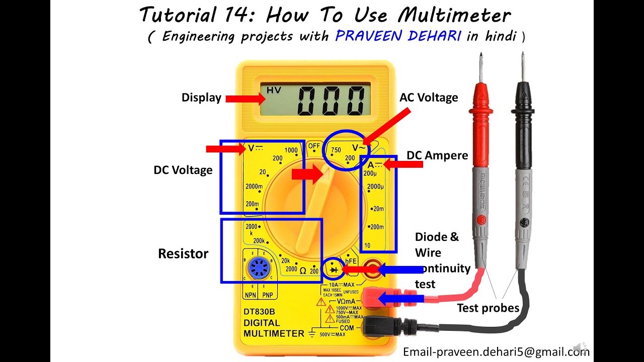
Let's break down the essential parts.
How Does a Multimeter Work - Jameco Electronics
This article from Jameco Electronics clearly describes the main components of a multimeter.
Read the section "Basic Components of a Multimeter". Pay close attention to the descriptions of the Display, the Selection Knob (rotary switch), and the Ports (jacks) for the probes.
The three main ports you will typically find are:
- COM: The common or ground terminal. The black probe always plugs in here.
- VΩmA: The port for measuring Voltage (V), Resistance (Ω), or small currents (in milliamps, mA). The red probe goes here for most measurements.
- 10A (or similar): A special port used only for measuring large currents (up to 10 Amps). This port is internally connected to a low-resistance path protected by a separate, high-current fuse.
It is critically important to plug the probes into the correct ports for the measurement you intend to make. Incorrect placement is a common source of error and can damage the multimeter's internal fuses.
How To Use A Multimeter: The VERY Basics!
This video from the "Simple Electronics" channel provides a great introduction to the physical parts of the multimeter and includes crucial safety advice.
Watch the segment from the beginning until the safety warning. The presenter clearly shows how to connect the leads and gives a general overview of the jacks.
Measuring Resistance (Ω)
Measuring resistance is often the safest and simplest measurement, as it's performed on unpowered components.
The Principle: To measure resistance, the multimeter uses its internal battery to send a tiny, known current through the component. It then measures the resulting voltage drop across the component and calculates the resistance using Ohm's Law ().
The Procedure:
- Safety First: Disconnect Power. The circuit or component you are measuring must be unpowered. Measuring resistance on a powered circuit can damage your multimeter and give meaningless readings.
- Isolate the Component. For an accurate reading, the resistor should ideally be removed from the circuit. If you measure a resistor while it's connected to other components, the multimeter's test current can flow through multiple paths, and you'll be measuring the equivalent resistance of that network, not the individual resistor. This is analogous to unit testing in software development, where you test a function in isolation to verify its behavior without interference from the rest of the program.
- Configure the Multimeter:
- Plug the black probe into the COM jack.
- Plug the red probe into the VΩmA jack.
- Turn the rotary dial to the resistance section, marked with the omega symbol (Ω). If your meter has multiple ranges (e.g., 200, 2k, 20k), start with a range higher than you expect the resistance to be, and work your way down for better precision. If your meter is "auto-ranging," it will select the best range for you.
- Measure: Touch the tips of the probes to the two leads of the resistor. The polarity does not matter. The resistance will be displayed on the screen.
Electronic Basics #1: The Multimeter
The "GreatScott!" channel offers a clear and practical demonstration of measuring resistance and highlights the problem of measuring in-circuit.
Watch the segment on measuring resistance, paying close attention to the part where he shows the incorrect reading obtained when the resistor is still in the circuit. Then, watch the short demonstration of the continuity feature, which is essentially a fast, audible check for near-zero resistance.
Measuring Voltage (V)
Voltage is a measure of potential difference between two points. Therefore, you always measure voltage across a component or a part of a circuit.
The Principle: A voltmeter must be connected in parallel with the component you want to measure. To avoid altering the circuit's behavior, an ideal voltmeter has infinite internal resistance. Real multimeters have very high internal resistance (typically >10 MΩ). This high resistance ensures that the meter draws only a minuscule amount of current from the circuit, thus not significantly affecting the voltage it is trying to measure. This directly relates to the "loading effect" we discussed previously; the high resistance of the voltmeter minimizes this effect.
The Procedure:
- Power On: Voltage measurement is performed on a live, powered circuit.
- Configure the Multimeter:
- Ensure the black probe is in COM and the red probe is in VΩmA.
- Turn the dial to the DC Voltage section, marked with V-- or VDC. (The
V~or VAC setting is for AC voltage, which we will cover later). - As before, if your meter is manual-ranging, select a range higher than the voltage you expect to measure.
- Measure: Connect the probes in parallel with the component or across the two points where you want to measure the potential difference.
- Connect the red probe to the point you expect to be more positive.
- Connect the black probe to the point you expect to be more negative (often the circuit ground).
- If you reverse the probes, the measurement is still correct, but the display will show a negative value.
How To Use A Multimeter: The VERY Basics!
This video provides another excellent step-by-step guide, this time for measuring DC voltage.
Watch the section on testing for voltage. Notice how the measurement is taken while the circuit is powered and how reversing the probes on the battery simply changes the sign of the reading.
Measuring Current (A)
Measuring current is the most intrusive of the three basic measurements and the one that requires the most care.
The Principle: Current is the flow of charge through a point in a circuit. To measure it, you must insert the ammeter directly into the path of the current, forcing the current to flow through the meter. This means the ammeter is connected in series. For the meter not to impede the flow it's measuring, an ideal ammeter has zero internal resistance. Real multimeters have very low internal resistance in their current-measuring modes.
The Procedure:
- Power On: Like voltage, current is measured on a live circuit.
- CRITICAL: Reconfigure the Multimeter Probes.
- The black probe stays in COM.
- The red probe MUST be moved to a current jack. For small currents (mA), use the VΩmA jack if it's labeled for it. For larger currents, or if you are unsure, always start with the high-current jack (e.g., 10A) to avoid blowing a fuse.
- Configure the Dial:
- Turn the dial to the DC Current section, marked A-- or ADC.
- Select an appropriate range, starting high if you're unsure.
- Break the Circuit and Insert the Meter:
- Turn the power off temporarily.
- Find the point in the circuit where you want to measure the current flow.
- "Break" the circuit at that point (e.g., by lifting one leg of a component).
- Turn the power back on.
- Connect the multimeter probes to bridge the gap you created, placing the meter in series with the load. The current will now flow out of the circuit, through the red probe, through the meter, out the black probe, and back into the circuit.
- CRITICAL: Return the Probe! As soon as you are finished measuring current, turn the power off and move the red probe back to the VΩmA jack. If you forget and try to measure voltage with the probe in the current jack, you will create a short circuit across your power source through the meter's low-resistance current shunt, which will almost certainly blow the meter's fuse and could damage your circuit.
How To Use A Multimeter: The VERY Basics!
This final segment clearly explains the complex but essential process of measuring current, including the warnings about fuses and probe placement.
Watch carefully from the beginning of the current measurement section. Pay special attention to how the circuit is broken to insert the meter in series, the use of the different current jacks, and the final warning about why you must move the probe back after you are done.
Conclusion
You have now learned the fundamentals of using a digital multimeter, the single most important tool for any electronics practitioner. By mastering this skill, you can verify your theoretical calculations, diagnose problems, and truly understand what is happening inside your circuits.
Key Takeaways:
- Anatomy: Understand the display, rotary switch, and probe jacks (COM, VΩmA, 10A).
- Resistance (Ω):
- Circuit must be POWER OFF.
- Measure OUT OF CIRCUIT (component isolated).
- Probes in COM and VΩmA.
- Voltage (V):
- Circuit must be POWER ON.
- Measure IN PARALLEL (across components).
- Probes in COM and VΩmA.
- Current (A):
- Circuit must be POWER ON.
- Measure IN SERIES (break the circuit and insert the meter).
- Move the red probe to a CURRENT JACK (A or mA).
- Always return the probe to the VΩmA jack when finished!
This lesson concludes our module on DC circuit analysis. You've built a solid foundation covering Ohm's Law, Kirchhoff's Laws, circuit simplification with Thévenin's theorem, and now, practical measurement with a multimeter.
In our next module, we will expand our component library by introducing capacitors and inductors. These components introduce the element of time to circuit behavior, storing and releasing energy in ways that allow us to build filters, timers, and the foundations of the power conversion circuits you're interested in for your robotics and IoT projects.