Introduction
Welcome back! In our last lesson, you created a comprehensive IP Address Management (IPAM) document for Aperture Logistics. This blueprint meticulously maps each VLAN to its corresponding subnet and formally defines the default gateway IP address for every segment. We have the "what" and the "where" on paper.
Today, we transition from paper planning to architectural design. The learning outcome for this lesson is to define the L3 routing topology, including SVI placement and IP assignments. We'll answer the critical questions: Which physical device will host these gateway IP addresses? And how will these devices connect to each other to enable routing across the entire network?
This is where your work as an architect truly begins, moving beyond simple configuration to making foundational design decisions. We'll establish the boundary between our Layer 2 and Layer 3 domains and bring our network's routing structure to life.
The L2/L3 Boundary: A Core Design Decision
The most fundamental decision in a campus network design is determining where Layer 2 (switching) ends and Layer 3 (routing) begins. This decision impacts scalability, convergence time, and complexity.
To understand the options, let's explore a high-level design article.
This article from Network Direction, 'Hierarchy Design Part 1', discusses different campus design topologies. We'll focus on the two most prevalent models to understand our choices.
Read the introduction under 'Switching and Routing in the Access Layer'. Then, read the sections 'Routed Access Layer' and 'Layer-2 (AKA, Multi-Tier)'. Focus on the key differences: in one model, the access switch itself is a router; in the other, routing is centralized at the distribution layer.
As you read, you'll see two primary models:
- Routed Access: Each access-layer switch is a Layer 3 device. The uplink to the distribution layer is a routed (L3) port. The default gateway for hosts connected to that switch resides on the switch itself. This model offers very fast convergence and simplifies the topology by eliminating L2 loops and spanning-tree, but requires L3-capable switches everywhere.
- L2 Access / L3 Distribution (Multi-Tier): The access layer is purely Layer 2. Access switches connect to the distribution layer via L2 trunk ports. All routing intelligence is centralized on one or more L3 distribution switches. This is a very common, flexible, and cost-effective design for many enterprise environments.
For our Aperture Logistics design, we will adopt the L2 Access / L3 Distribution model. This aligns well with the scale of the organization (~1000 users) and centralizes the complex routing functions, making management more straightforward. In this model, one or more powerful L3 switches at the core/distribution layer will be the routing workhorse for the entire campus.
The Layer 3 Switch: Your Network's Routing Hub
Since we've chosen to centralize routing, the Layer 3 switch is the star of the show. But what exactly is it? It's a hybrid device that combines the high-speed hardware of a switch with the IP-smarts of a router.
This video from Jeremy's IT Lab provides a fantastic explanation.
Free CCNA | VLANs (Part 3) | Day 18 | CCNA 200-301 Complete Course
This video clearly explains what a Layer 3 (or multilayer) switch is and contrasts it with a traditional router-on-a-stick design, which is conceptually similar but less scalable.
Watch from 09:47 to 15:12. Pay close attention to the two key capabilities mentioned: Switched Virtual Interfaces (SVIs) and routed ports. Also, note the performance benefit of routing traffic directly on the switch instead of sending it to an external router and back.
As the video highlights, an L3 switch can:
- Route between VLANs using Switched Virtual Interfaces (SVIs).
- Form L3 connections to other routing devices using Routed Ports.
Let's look at how we use these two features to build our topology.
SVI Placement and IP Assignment
The SVI is the virtual Layer 3 interface for a VLAN. For every VLAN in your IPAM that needs to communicate with other networks, you will create a corresponding SVI on your L3 distribution switch. The IP address you assign to this SVI is the default gateway from your IPAM document.
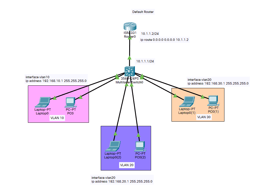
Configuration Steps
Configuring an SVI is straightforward, but there are a few critical steps.
Inter-VLAN Routing using Layer 3 Switches
Let's review the configuration steps in this Cisco Press article. It provides a clear, step-by-step guide.
Read the section 'Layer 3 Switch Configuration (4.3.3)'. This covers the four essential steps: create the VLAN, create the SVI, configure access ports (on the access switch), and enable IP routing.
The four key steps are:
- Create the VLAN:
vlan [vlan-id] - Create the SVI:
interface vlan [vlan-id] - Assign the IP address:
ip address [gateway-ip] [subnet-mask] - Enable IP Routing:
ip routing(in global configuration mode)
The ip routing command is absolutely crucial. Without it, the device will not build a routing table and will not forward traffic between subnets, even if the SVIs are configured correctly.
This is a common point of failure in real-world deployments. The next video demonstrates not only the SVI configuration but also what happens if you forget this vital command.
LAN 3-Tier Architecture: VLAN, HSRP, EtherChannel, Routing | Lab CCNA 200-301
This lab from KBTrainings shows a more complex, redundant setup. We'll focus on the core SVI configuration and the troubleshooting step where the engineer realizes routing isn't working.
Watch from 12:32 to 18:35. Notice how he first configures the SVIs with their IP addresses (13:30). When ping fails, he checks the routing table (show ip route) at 17:30 and realizes it's empty, leading him to enable ip routing at 18:05. This is a classic troubleshooting sequence.
Routed Ports: Connecting to the Outside World
SVIs handle routing inside your campus between your VLANs. But how does your campus talk to other networks, like the internet or another site? For this, we use routed ports.
A routed port is a physical switch port that has been converted to operate like a router interface. You do this with the no switchport command in interface configuration mode. Once converted, you can assign an IP address directly to the port, just like on a router. These are typically used for point-to-point links between L3 devices.
For Aperture Logistics, we will use a routed port on our core L3 switch to connect to an edge router that provides internet access. This link will use one of the /30 subnets from our IPAM, like 10.254.0.0/30.
Let's see how this is configured.
Free CCNA | VLANs (Part 3) | Day 18 | CCNA 200-301 Complete Course
We'll return to Jeremy's IT Lab to see the configuration of a routed port and a default route.
Watch from 15:12 to 19:37. Focus on the no switchport command that converts the L2 port to an L3 interface, allowing an IP address to be assigned. Also, notice the configuration of the default route (ip route 0.0.0.0 0.0.0.0 ...), which tells the L3 switch where to send all traffic destined for unknown networks (i.e., the internet).
The Aperture Logistics L3 Topology
Let's consolidate everything we've learned into a defined topology for Aperture Logistics.
- Design Model: L2 Access / L3 Distribution.
- Core Device: A single (for now) L3 switch, let's call it
D1. This switch will be the routing hub. - SVI Placement: All SVIs for our user, voice, server, and IoT VLANs (from the IPAM) will be configured on
D1.D1will host the default gateway for every internal subnet. - Access Layer: Access switches (
A1,A2, etc.) will be L2 devices. They will connect toD1via L2 trunk links, carrying all necessary VLANs. - Internet Connectivity:
D1will connect to an edge router (R1) via a dedicated routed port. This point-to-point link will be addressed with a/30subnet (e.g.,10.254.0.0/30).D1will have a default route pointing toR1.
Here's a simple text diagram of our defined topology:
                  +----------------+
                  |  Internet (R1) |
                  | 10.254.0.2/30  |
                  +-------+--------+
                          |
                          | (Routed Port, L3 Link)
                          |
                  +-------+--------+
                  |  D1 (L3 Switch)|
                  | 10.254.0.1/30  |
                  |----------------|
                  | SVI VLAN 110: 10.10.0.1/24
                  | SVI VLAN 80:  10.20.0.1/23
                  | SVI VLAN 90:  10.20.2.1/23
                  | ... (all other SVIs) ...
                  +-------+--------+
                          |
               +----------+----------+
               | (Trunk Link, L2)  | (Trunk Link, L2)
               |                     |
      +--------+-------+     +-------+--------+
      | A1 (L2 Switch) |     | A2 (L2 Switch) |
      +----------------+     +----------------+
           |       |              |       |
       (VLAN 110) (VLAN 80)   (VLAN 110) (VLAN 135)
This design clearly defines our L3 topology, SVI placement on device D1, and IP assignments for both the internal gateways (SVIs) and the external-facing link (routed port).
Conclusion
In this lesson, you have defined a complete Layer 3 routing topology. You moved beyond a simple list of subnets and gateways to architect the logical structure of the network. This is a critical skill for any network professional, bridging the gap between planning and implementation.
Key Takeaways:
- The L2/L3 boundary is a primary design decision. For our campus, we chose a centralized L3 Distribution model.
- Switched Virtual Interfaces (SVIs) are the L3 interfaces for our VLANs. In our design, they are all placed on the central L3 distribution switch.
- The
ip routingcommand is mandatory to enable a multilayer switch to perform routing functions. - Routed Ports (
no switchport) are used to create L3 point-to-point links between routing devices, such as connecting our core switch to the internet edge router.
Preview of the Next Lesson:
We've designed the road system, and now it's time to watch the traffic. In the next lesson, we will trace the packet flow for a host in one VLAN communicating with a host in another VLAN via an L3 switch. This will solidify your understanding of how frames and packets are processed as they move through the architecture you just designed.