Introduction
Welcome back. In our last lesson, we finalized and audited our IP Address Management (IPAM) plan, ensuring it was complete, accurate, and free of overlapping subnets. A key step in that process was assigning a default gateway IP address for each subnet. We noted that this IP would live on something called a Switched Virtual Interface (SVI).
Today, we're going to dive into exactly what an SVI is. This lesson directly addresses the learning outcome: to explain the function of a Switched Virtual Interface (SVI) as a VLAN's Layer 3 gateway.
You're used to configuring IP addresses on physical interfaces. The mental shift here is that we're assigning an IP address to a logical interface that represents an entire VLAN. This concept is the cornerstone of modern, scalable network designs that use Layer 3 switches for routing, which is central to your goal of building large, efficient architectures.
We will cover:
- The Problem: Why do we need a mechanism for devices in different VLANs to communicate?
- The Solution: What is an SVI and how does it function as a gateway?
- The Process: How does a Layer 3 switch use SVIs to route a packet from one VLAN to another?
Part 1: Why Inter-VLAN Routing is Necessary
As we've established, VLANs are powerful for segmentation. They create separate Layer 2 broadcast domains. But this isolation comes with a side effect: by default, a device in VLAN 10 cannot communicate with a device in VLAN 20, even if they are connected to the same physical switch. They are in different broadcast domains and, as per our IPAM, different IP subnets.
To bridge this gap, you need a device that can operate at Layer 3—a router.
Historically, one common method to solve this was called "Router on a Stick" (ROAS).
Switched Virtual Interface (SVI) and Integrated Routing and Bridging (IRB)
To understand why SVIs are the modern standard, it helps to first understand the problem they were designed to solve. This podcast transcript from Packet Pushers provides an excellent, non-technical explanation of the older 'Router on a Stick' method.
Please read the section of the transcript where the hosts discuss the 'Router on a Stick' concept. This section starts around the 7:22 timestamp with 'So in the really early days of Ethernet...' and continues until about the 16:17 timestamp, ending with '...you’re going out the switch to a router back into the same switch.' Focus on understanding the inefficient traffic path: from the switch, up to an external router, and then back down to the same switch just to get to a different VLAN.
As you just read, the ROAS approach is inefficient. Traffic has to physically leave the switch, travel to a router, get routed, and travel back to the switch. This creates a performance bottleneck on the single link to the router.
The modern, more efficient solution is to perform the routing function inside the switch itself. This is the primary capability of a Layer 3 Switch.
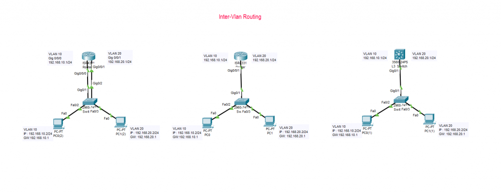
Part 2: What is a Switched Virtual Interface (SVI)?
A Layer 3 switch performs internal routing using Switched Virtual Interfaces (SVIs).
An SVI is a virtual Layer 3 interface that is associated with a single VLAN on a switch. It is not a physical port; it's a logical interface you create in the switch's configuration.
The key function of an SVI is to be the default gateway for its VLAN.
Let's break this down:
- You create a VLAN, say
vlan 10. - You create a corresponding SVI,
interface Vlan10. - You assign an IP address from the VLAN 10 subnet to this SVI (e.g.,
192.168.10.1/24). - All host devices in VLAN 10 are configured to use
192.168.10.1as their default gateway.
When a host in VLAN 10 needs to send traffic to a different subnet (like VLAN 20), it sends the traffic to its gateway—the SVI. The Layer 3 switch then takes over and routes the packet internally.
How to Configure a Switch Virtual Interface (SVI)
This video from Kevin Wallace provides a very clear and direct explanation of how an SVI acts as the default gateway for devices within its VLAN.
Please watch the segment from 02:07 to 04:21. Pay close attention to the animation showing the PC sending traffic destined for another VLAN to its default gateway, which is the IP address of the SVI on the switch.
This is the 1:1 relationship we discussed in the previous module: one VLAN maps to one IP subnet, and that subnet's gateway is one SVI.
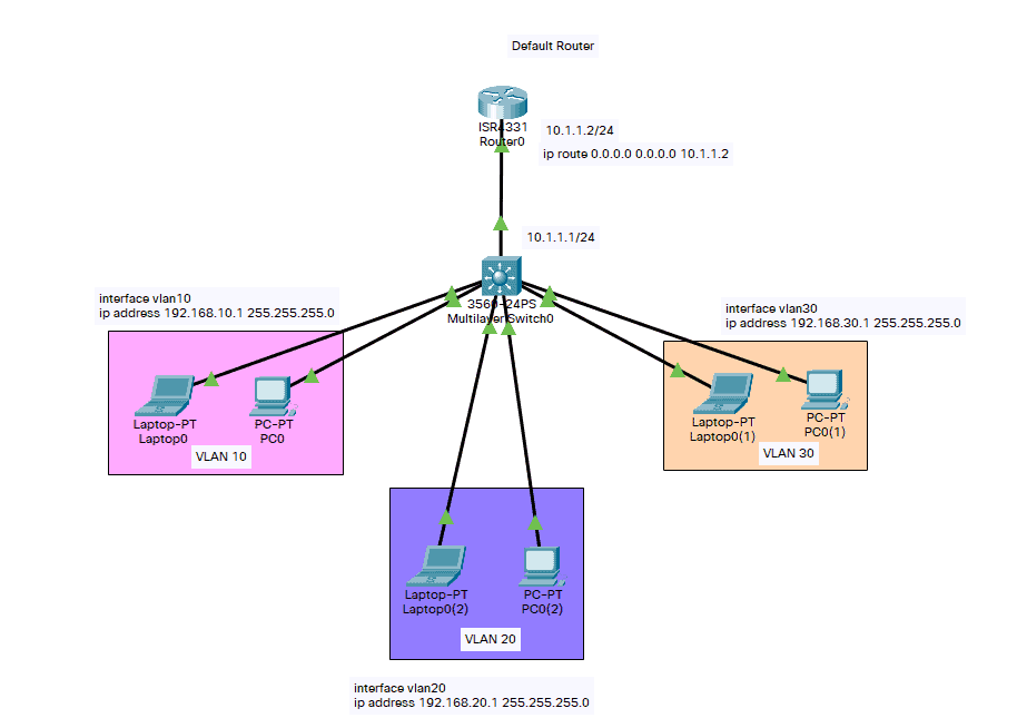
Part 3: The Inter-VLAN Routing Process
Now let's trace a packet's journey to solidify the concept. Imagine PC-A (192.168.10.10) in VLAN 10 wants to ping PC-D (192.168.20.20) in VLAN 20. Both are connected to the same Layer 3 switch.
- Host Decision: PC-A compares PC-D's IP address to its own subnet (
192.168.10.0/24). It determines PC-D is on a different network. Therefore, it must send the packet to its default gateway (192.168.10.1). - Layer 2 Framing: PC-A needs the MAC address of its gateway. It sends an ARP request for
192.168.10.1. The L3 switch's SVI for VLAN 10 (interface Vlan10) receives this request and replies with its own virtual MAC address. - Forward to Gateway: PC-A now creates an Ethernet frame.
- Source MAC: PC-A's MAC
- Destination MAC: The SVI's MAC
- Source IP:
192.168.10.10 - Destination IP:
192.168.20.20
The frame is sent onto the wire and received by the switch.
- Routing Decision: The switch sees the frame is addressed to its own SVI 10 MAC address. This tells the switch to act as a router. It de-encapsulates the frame and looks at the Layer 3 information. The destination IP is
192.168.20.20. The switch checks its routing table. Because it has an active SVI in VLAN 20 (interface Vlan20with IP192.168.20.1/24), it knows the192.168.20.0/24network is directly connected. - Layer 2 Re-framing: The switch now needs to forward the packet to PC-D. It sends an ARP request for
192.168.20.20out into VLAN 20. PC-D responds with its MAC address. - Forward to Host: The switch creates a new Ethernet frame.
- Source MAC: The SVI 20's MAC
- Destination MAC: PC-D's MAC
- Source IP:
192.168.10.10(Note: L3 addresses don't change) - Destination IP:
192.168.20.20
The switch forwards this new frame out of the port connected to PC-D.
This entire process happens at hardware speed within the switch's backplane, making it far more efficient than Router-on-a-Stick.
This animated video offers a simple, visual walkthrough of the packet flow we just described.
Watch from 04:05 to 04:43. This short clip animates the exact process of a packet going to its default gateway (the SVI), being routed by the L3 switch, and then forwarded to the destination host in the other VLAN.
Part 4: Configuration Context
For someone with your CLI background, seeing the configuration ties it all together. Here is how you would configure the SVIs for VLAN 10 and VLAN 20 from our example.
Inter-VLAN Routing using Layer 3 Switches (4.3) - Cisco Press
This article from Cisco Press shows the exact commands used to configure SVIs on a Cisco Layer 3 switch. It's a practical application of the theory we've discussed.
Read through the configuration steps, specifically focusing on 'Step 2. Create the SVI VLAN interfaces' and 'Step 4. Enable IP routing'. Notice the familiar interface command, but applied to a VLAN instead of a physical port. Pay special attention to the ip routing global command – this is a critical step that 'turns on' the Layer 3 capabilities of the switch.
A quick summary of the key configuration steps:
- Define your VLANs (
vlan 10,vlan 20). - Create the SVI for each VLAN (
interface Vlan10). - Assign the gateway IP address (
ip address 192.168.10.1 255.255.255.0). - Enable the interface (
no shutdown). - Crucially, enable routing globally on the switch (
ip routing). Without this command, the switch will not route packets between VLANs, even if the SVIs are configured.
A final point: "SVI" is largely a Cisco term. Other vendors have different names for the same concept. For instance, Juniper calls it an "Integrated Routing and Bridging" (IRB) interface. The function is identical.
Conclusion
You now understand the fundamental mechanism for routing traffic in a modern segmented network. The SVI is the bridge between the Layer 2 world of VLANs and the Layer 3 world of IP routing.
Key Takeaways:
- Hosts in different VLANs cannot communicate without a Layer 3 routing function.
- A Layer 3 switch integrates this routing function, which is more efficient than using an external router (ROAS).
- A Switched Virtual Interface (SVI) is a logical Layer 3 interface on a switch that is tied to a specific VLAN.
- The primary function of an SVI is to serve as the default gateway for all devices within its associated VLAN.
- When a host sends a packet to a different subnet, it forwards the packet to the MAC address of its gateway SVI. The switch then uses its internal routing engine to forward the packet to the destination VLAN.
Next Steps
We've focused on the SVI itself as the gateway interface. In our next lesson, we will zoom out and discuss the role of a core or distribution layer L3 switch in routing traffic between VLANs. We'll look at where these switches fit in a typical network hierarchy and how they handle traffic flow in a larger, multi-switch environment.