Introduction
Hello and welcome back. In the previous lesson, we established that a Switched Virtual Interface (SVI) acts as the virtual Layer 3 gateway for a VLAN, enabling devices to send traffic outside their local subnet.
This lesson zooms out from the single interface to the device itself. We'll answer the question: Where does this Layer 3 switch fit into a larger network, and what is its specific job? This directly addresses the learning outcome: to describe the role of a core or distribution layer L3 switch in routing traffic between VLANs.
You're already familiar with configuring individual devices. Today, we'll place those devices into a structured, hierarchical design, which is essential for building the scalable and maintainable architectures you're aiming for. We will see how a strategically placed L3 switch becomes the central nervous system for communication between all your carefully planned subnets and VLANs.
Part 1: The Hierarchical Network Model
Before we discuss the L3 switch's role, we need to understand the blueprint for a scalable network. Large networks aren't just a random sprawl of switches; they are typically built using a three-tier hierarchical model. This design provides predictability, scalability, and modularity.
The three layers are:
- Access Layer: The "edge" of the network where end-user devices like computers, printers, and phones connect. This layer is primarily concerned with Layer 2 operations, like assigning devices to specific VLANs.
- Distribution Layer: This layer aggregates traffic from multiple access layer switches. It acts as a boundary between Layer 2 and Layer 3 and is a critical point for applying network policies.
- Core Layer: The high-speed backbone of the network. Its sole purpose is to switch and route traffic between distribution layer devices as fast as possible.
To understand the context for our L3 switch, let's review the functions of these three layers. This article from NetworkDirection provides a concise and clear overview of the model.
Please read the sections titled 'Access', 'Distribution', and 'Core'. For each layer, focus on its primary function and how it connects to the other layers.
As you've just read, the Distribution Layer is the primary candidate for placing our L3 switch. It's the logical place to aggregate VLANs from the access layer and handle the routing between them.
Part 2: The L3 Switch as a Distribution Layer Device
Imagine a building with several floors. Each floor has a few access layer switches connecting dozens of users in different departmental VLANs (e.g., VLAN 10 for Sales, VLAN 20 for Engineering). These access switches are connected via trunk links to a powerful L3 switch in the building's wiring closet. This L3 switch is serving as the distribution layer.
Here's its role:
- It is the routing hub for all local VLANs. It holds the SVI for every VLAN in that building.
- It connects the Layer 2 segments to the Layer 3 network. All traffic that needs to go from one VLAN to another must travel up from the access switch to the distribution L3 switch to be routed.
The diagram below illustrates this. PC1 (VLAN 10) and PC2 (VLAN 20) are connected to the same Layer 2 access switch (S2). For them to communicate, the traffic must flow up to the multilayer switch (S1) where the routing decision is made.
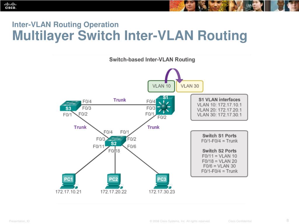
This centralization of routing is incredibly efficient. Instead of using an external router, the L3 switch performs this function internally using specialized hardware (ASICs), allowing it to route at line rate, or the maximum speed of its physical ports.
This short animation provides a great visual summary of how an L3 switch uses SVIs to route between VLANs in this role.
Watch the segment from 03:16 to 04:43. Pay close attention to how the packet from one VLAN is sent to the default gateway (the SVI on the L3 switch), which then routes it to the SVI of the destination VLAN.
Part 3: The "Collapsed Core" Design
For the scale you're working with (~1000 devices, a couple of buildings), a full three-tier design might be overkill. A very common and practical approach is the Collapsed Core model.
In this design, the Core and Distribution layer functions are combined into a single, powerful pair of L3 switches. This model is simpler and more cost-effective for small to medium-sized enterprises while still providing centralized routing and scalability.

In a collapsed core architecture, your main L3 switch (or a redundant pair) becomes the heart of the network. It not only routes between all the VLANs from your access switches but also connects to other network blocks or the internet. This is the design you will most likely be implementing.
Let's revisit the 'Hierarchical Network Model' article to see how the Collapsed Core model works and when it's appropriate.
Read the section titled 'Two-Tier Design: The Collapsed Core'. Focus on how the core and distribution layers merge onto the same physical switches and why this is suitable for networks that don't have a massive number of distribution blocks.
Part 4: Why This Role is Critical
Understanding the L3 switch's role as a distribution/core device is fundamental to good network design.
- Performance and Scalability: As mentioned, L3 switches route using specialized hardware, making them far faster than the old "router-on-a-stick" method. This is essential for handling the traffic load of hundreds or thousands of devices.
- Centralized Policy Enforcement: Since all inter-VLAN traffic must pass through this central L3 switch, it's the perfect choke point to enforce security policies. In a future module, we'll see how to apply Access Control Lists (ACLs) to the SVIs on this switch to control exactly which subnets can talk to each other.
- Simplified Management: Having all your default gateways on a central device (or redundant pair) simplifies IP address management and troubleshooting. When there's a routing issue, you know exactly where to start looking.
Inter-VLAN Routing using Layer 3 Switches (4.3) - Cisco Press
This Cisco Press article reinforces the scalability advantage of using L3 switches for inter-VLAN routing in enterprise networks.
Please read the first section, 'Layer 3 Switch Inter-VLAN Routing (4.3.1)'. Note the emphasis on how L3 switches are the standard in enterprise campus LANs because they are faster and more scalable than router-on-a-stick.
Conclusion
In this lesson, we placed the L3 switch into its proper architectural context. It's not just another box in the rack; it's the intelligent routing engine at the center of your segmented network.
Key Takeaways:
- Large networks follow a hierarchical model (Access, Distribution, Core) for scalability and manageability.
- An L3 switch is most often deployed at the Distribution layer to aggregate traffic from access switches and perform inter-VLAN routing.
- In this role, the L3 switch hosts the SVIs (gateways) for the VLANs defined in the access layer.
- For many enterprise networks, a Collapsed Core design is used, where the distribution and core layers are combined onto a single set of powerful L3 switches.
- This centralized routing point is vital for network performance, simplified management, and applying security policies like ACLs.
Next Steps
Now that you understand what an SVI is and where the L3 switch that hosts it lives, our next lesson will get highly specific. We will trace the packet flow for a host in one VLAN communicating with a host in another VLAN via an L3 switch. We'll follow a single packet, hop-by-hop, from the source PC, through the access and distribution switches, and to its final destination, examining how the IP and MAC addresses change along the way.