Introduction
Welcome back. In our last lesson, we traced the journey of a packet between two VLANs on a single Layer 3 switch. We saw how the switch uses Switched Virtual Interfaces (SVIs) to act as a gateway, rewriting MAC addresses at Layer 2 while preserving the original IP addresses at Layer 3.
Today, we move from a single device to a realistic, multi-switch architecture. The central question we'll answer is: in a large network with dozens of switches, where should the SVIs—the Layer 3 gateways for your VLANs—actually live? This is a fundamental design decision with significant implications for performance, scalability, and flexibility.
Our learning outcome is to plan SVI placement and IP addressing in a multi-switch L3 topology. We'll explore the two dominant design models, weigh their pros and cons, and then establish best practices for assigning IP addresses to these critical interfaces.
The Core Design Question: Centralized vs. Distributed SVIs
In a typical three-tier hierarchical network (Core, Distribution, Access), there are two primary models for placing your SVIs.
- Layer 2 Access (Centralized SVIs): The access layer operates purely at Layer 2, trunking all VLANs up to the distribution layer. The SVIs for all user VLANs are configured centrally on the distribution switches.
- Layer 3 Access (Distributed SVIs): The links between the access and distribution layers are Layer 3 routed links. Each access switch (or switch stack) hosts the SVIs only for the VLANs connected directly to it.
The choice between these two models involves a crucial trade-off between flexibility and scalability. The following video offers an excellent deep dive into this exact dilemma.
ENCOR - Enterprise Network Design
This video from KishSquared's ENCOR series provides a detailed, real-world comparison of Layer 2 versus Layer 3 access layer designs. It gets to the heart of why you would choose one model over the other.
Watch the segment from 30:00 to 45:30. Pay close attention to the discussion of the pros and cons of each model, specifically concerning Spanning Tree Protocol (STP), broadcast domains, and the requirement for Layer 2 adjacency for certain applications.
Let's break down the key points from that video.
Model 1: Layer 2 Access (Centralized SVIs)
This is the most common design in enterprise campus networks.
- Topology: Access switches act as simple Layer 2 devices. They are connected to distribution switches via 802.1Q trunk links that carry multiple VLANs.
- SVI Placement: All SVIs for user VLANs (e.g.,
interface Vlan10,interface Vlan20) are configured on the distribution layer switches. - Packet Flow: A packet from Host A in VLAN 10 going to Host B in VLAN 20 travels up the trunk to the distribution switch. The distribution switch routes the packet from its VLAN 10 SVI to its VLAN 20 SVI and sends it back down the appropriate trunk link to Host B's access switch.
Pros:
- Maximum Flexibility: A single VLAN (and its corresponding subnet) can be stretched across multiple access switches and wiring closets throughout a building. This is essential for user mobility and applications that require devices to be on the same Layer 2 domain, regardless of physical location.
Cons:
- Spanning Tree Protocol (STP) Dependency: To prevent loops in the redundant L2 topology, STP must be running. This means some links will be in a blocking state, leading to potentially unused bandwidth. More importantly, an STP failure can cause a catastrophic loop that brings down the entire L2 domain (all connected access and distribution switches).
- Large Broadcast Domains: Broadcasts from any host in a VLAN are flooded across all switches where that VLAN exists, consuming bandwidth and CPU on every device.
To mitigate the risks of STP, modern designs often use technologies that bundle physical switches into a single logical unit, such as Cisco's StackWise (for stackable switches) or Virtual Switching System (VSS). This can create a loop-free logical topology, allowing all uplinks to be active in an EtherChannel while still providing redundancy.
Model 2: Layer 3 Access (Distributed SVIs)
This design, often called "routed access," pushes Layer 3 intelligence down to the edge of the network.
- Topology: The links between access and distribution switches are Layer 3 routed ports, typically using
/30or/31subnets. - SVI Placement: Each access switch (or stack) hosts the SVIs for the VLANs it serves. For example, if users in wiring closet A need VLAN 10 and VLAN 30, the access switch in closet A will have
interface Vlan10andinterface Vlan30configured. - Packet Flow: If two hosts on the same access switch need to communicate across VLANs, the routing is handled locally by that switch. If a host needs to reach a different part of the network, it sends its packet to its local SVI, and the access switch routes it up to the distribution layer.
Pros:
- Scalability & Stability: STP is eliminated between the access and distribution layers. The failure domain is much smaller; a problem on one access switch is unlikely to affect others. Broadcasts are contained within a single switch.
- Faster Convergence: Routing protocols like OSPF or EIGRP can detect link failures and reconverge much faster than STP.
Cons:
- Inflexibility: A VLAN and its subnet are confined to a single access switch or stack. You cannot have the same VLAN in two different wiring closets. As the video pointed out, if a department later deploys an application that requires Layer 2 adjacency across closets, this design must be completely re-engineered.
Planning IP Addresses for SVIs
Once you've decided where your SVIs will live (typically the distribution layer for campus networks), the next step is to plan their IP addresses. This is a straightforward but critical task.
- Rule: The IP address of an SVI is the default gateway for all devices in that VLAN/subnet. Therefore, the SVI's IP address must belong to the subnet it is serving.
- Convention: For consistency and predictability, it's a best practice to use the first or last usable IP address in the subnet for the gateway.
This Cisco guide outlines several standards for IP address planning.
This section of the Cisco IP Addressing Guide provides excellent, practical standards for assigning IP addresses within a subnet, including a specific recommendation for gateways.
Read the section 'Procedure 1: Define Addressing Standards'. Focus on the bullet points under 'Step 1', particularly the recommendations for assigning addresses to routers and gateways.
A common and highly recommended standard is to assign the first usable IP address of any given subnet to its SVI. For example, in the subnet 192.168.10.0/24, the SVI interface Vlan10 would be assigned 192.168.10.1.
If you are using a First Hop Redundancy Protocol (FHRP) like HSRP between two distribution switches, the convention is often:
- Virtual IP (Gateway):
.1(e.g.,192.168.10.1) - Distribution Switch 1 SVI:
.2(e.g.,192.168.10.2) - Distribution Switch 2 SVI:
.3(e.g.,192.168.10.3)
This consistent scheme makes troubleshooting much easier. When you see a .1 address in a trace, you immediately know it's a gateway.
The following table from a campus design guide illustrates a typical centralized SVI plan. Note how each SVI (the default gateway) is placed on the core switches (acting as a collapsed core/distribution layer) and uses the .1 address of its respective subnet.
Hybrid Campus LAN Design Guide - Network Segments Table
This table from the Hybrid Campus LAN Design Guide shows a clear mapping of network segments to VLAN IDs, subnets, and default gateways. Note the consistent use of the .1 address for the gateway SVI, which is hosted on the core switches.
Practical Exercise: Design an SVI and IP Plan
Now, let's apply these concepts. The image below shows a standard hierarchical network. Your task is to plan the SVI placement and create an IP addressing scheme.
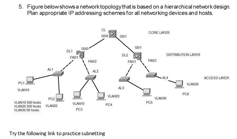
Scenario:
- You are assigned the parent IP block
172.20.0.0/16. - You decide to use a Layer 2 Access model, placing your SVIs on the Distribution layer switches.
- The host requirements are as specified in the diagram:
- VLAN 10 (Sales): 500 hosts
- VLAN 20 (Engineering): 200 hosts
- VLAN 30 (Marketing): 60 hosts
- You also need subnets for the routed point-to-point links between the Core and Distribution switches. Assume you need two such links.
Your Task:
- Calculate Subnet Sizes: Using your VLSM skills, determine the appropriate CIDR prefix for each VLAN based on its host requirements. Remember to account for future growth. Also, choose an appropriate prefix for the point-to-point links (a
/30is standard). - Allocate Subnets: Starting with the largest requirement first, allocate non-overlapping subnets from the
172.20.0.0/16block. - Create an IPAM Table: Document your plan in a table with the following columns:
- VLAN ID / Link Name
- Department
- Network Address & Prefix
- Usable IP Range
- Broadcast Address
- Gateway (SVI) IP Address
Take about 15 minutes to complete this. Once you're done, check your work against the solution below.
Click to see a possible solution
Here is one possible way to structure the IP plan. Your specific address choices may vary, but the subnet sizes should be similar.
1. Subnet Sizing:
- VLAN 10 (Sales): 500 hosts require 9 host bits (). This means a
32 - 9 = /23mask. - VLAN 20 (Engineering): 200 hosts require 8 host bits (). This means a
32 - 8 = /24mask. - VLAN 30 (Marketing): 60 hosts require 6 host bits (). This means a
32 - 6 = /26mask. - Core-Distro Links: Point-to-point links require 2 host addresses. This means a
/30mask.
2. IPAM Table:
| VLAN ID / Link | Department | Network Address & Prefix | Usable IP Range | Broadcast Address | Gateway (SVI) IP Address |
|---|---|---|---|---|---|
| 10 | Sales | 172.20.0.0/23 |
172.20.0.1 - 172.20.1.254 |
172.20.1.255 |
172.20.0.1 |
| 20 | Engineering | 172.20.2.0/24 |
172.20.2.1 - 172.20.2.254 |
172.20.2.255 |
172.20.2.1 |
| 30 | Marketing | 172.20.3.0/26 |
172.20.3.1 - 172.20.3.62 |
172.20.3.63 |
172.20.3.1 |
| Core-Distro 1 | Infrastructure | 172.20.3.64/30 |
172.20.3.65 - 172.20.3.66 |
172.20.3.67 |
N/A (Routed Port) |
| Core-Distro 2 | Infrastructure | 172.20.3.68/30 |
172.20.3.69 - 172.20.3.70 |
172.20.3.71 |
N/A (Routed Port) |
Conclusion
In this lesson, we elevated our understanding of inter-VLAN routing from a single device to a full network topology. We established that deciding where to place your SVIs is a critical design choice that balances flexibility against stability.
Key Takeaways:
- SVI Placement: The two main models are Layer 2 Access (SVIs on distribution, flexible, most common for campus) and Layer 3 Access (SVIs on access, scalable, but rigid).
- Trade-offs: The L2 access model stretches VLANs across the campus but relies on STP, creating larger failure domains. The L3 access model contains failures and broadcasts but prevents VLANs from spanning multiple switches.
- SVI Addressing: The SVI for a VLAN acts as its default gateway. Its IP address must be within the VLAN's subnet.
- Best Practice: For consistency, always assign the first (or last) usable IP address in a subnet to its gateway SVI (e.g.,
192.168.10.1for the192.168.10.0/24subnet).
Next Steps
We've now designed our SVI placement and addressing plan. The final piece of this puzzle is ensuring the end hosts actually use these gateways. In our next lesson, we will focus on how to designate the appropriate default gateway for hosts within a VLAN, which will primarily involve configuring DHCP services to automatically provide clients with the correct gateway IP address.