Welcome to the first lesson of our second module. In the previous module, we built a solid foundation in C++ systems programming, culminating in understanding how a multi-file project is compiled and linked into an executable program. That executable file contains machine code—the raw binary instructions that a processor understands. Now, we shift our focus from the software to the hardware and ask: how does a processor actually run that code?
This lesson begins our exploration of computer architecture by examining the heart of a traditional computer, the Central Processing Unit (CPU). Your goal is to master high-performance computing, and to do that, you must first understand the fundamental principles of the "default" processor. The CPU's design philosophy, honed over decades, provides a crucial baseline against which we will later contrast the massively parallel architecture of the GPU.
Today, we will dissect the CPU's core operational loop, the fetch-decode-execute cycle, and explore pipelining, the fundamental technique modern CPUs use to introduce parallelism and dramatically increase performance.
1. The CPU's Fundamental Task: The Fetch-Decode-Execute Cycle
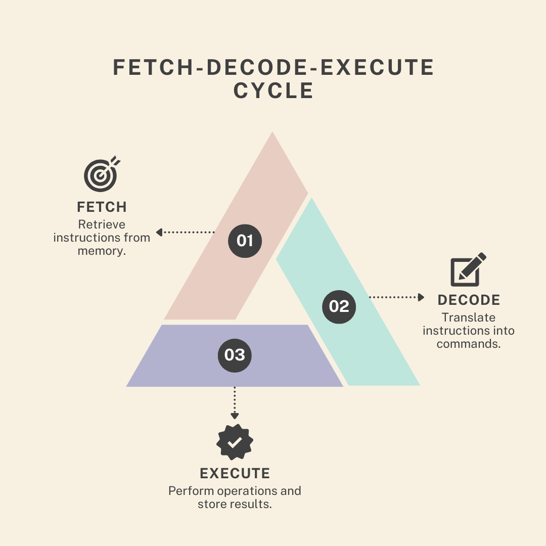
At its most basic level, a CPU's job is to execute a sequence of instructions. It does this by repeating a simple, three-step process known as the fetch-decode-execute cycle. Think of it like a chef meticulously following a recipe, one step at a time.
Let's watch a short video that introduces this fundamental concept.
The video "CPU Architecture Explained" by BitLemon provides a clear and concise introduction to the CPU's role and its core operational cycle.
Watch the first 40 seconds, which define the CPU and introduce the fetch-decode-execute cycle as its fundamental mode of operation.
The three stages are:
- Fetch: The CPU retrieves, or fetches, the next instruction from main memory (RAM). The address of this instruction is stored in a special high-speed memory location on the CPU called a register, specifically the Program Counter (PC). After fetching, the PC is updated to point to the next instruction.
- Decode: The fetched instruction, which is just a pattern of bits, is interpreted by the CPU's Control Unit (CU). The CU decodes the instruction to determine what operation needs to be performed (e.g., add, subtract, load data, store data) and which data is needed for the operation.
- Execute: The Arithmetic Logic Unit (ALU) performs the actual computation. This could be a mathematical operation (like addition), a logical operation (like AND/OR), or moving data between registers and memory.
This cycle repeats continuously, billions of times per second, allowing the CPU to work through the machine code of a program.
2. The Components of the Cycle
To understand the cycle in more detail, we need to know the key hardware components involved. These components work together like a well-coordinated team to process instructions.

Let's explore these components and their roles.
Let's return to the "CPU Architecture Explained" video to learn about the key functional units inside a CPU.
Watch the segment from CPU Components. This part provides an excellent overview of the four main units: the Arithmetic Logic Unit (ALU), the register file, the Load-Store Unit (LSU), and the Control Unit.
As the video explains, the main players are:
- Control Unit (CU): The project manager. It fetches instructions, decodes them, and directs the flow of data between the other components.
- Arithmetic Logic Unit (ALU): The computational engine. It executes all arithmetic (add, multiply) and logical (AND, OR, NOT) operations.
- Registers: A small set of extremely fast on-chip memory locations used to temporarily store data the CPU is actively working on. Key registers include:
- Program Counter (PC): Holds the memory address of the next instruction to fetch.
- Instruction Register (IR): Holds the current instruction being decoded and executed.
- General-Purpose Registers: Hold data (operands) for ALU operations.
- Buses: The electrical pathways that connect all these components and transfer data, addresses, and control signals between them.
The entire process is synchronized by a clock. Each "tick" of the clock (a clock cycle) triggers the next step in the operation. A CPU with a 4 GHz clock speed goes through 4 billion cycles per second.
In the simple, non-pipelined model, executing one instruction might take several clock cycles to complete the full fetch-decode-execute sequence. During this time, many of the CPU's components are idle. For example, while the ALU is busy executing an instruction, the fetch unit is doing nothing. This is highly inefficient.
3. Increasing Throughput with Pipelining
To solve this inefficiency, modern processors use a technique called pipelining. The core idea is inspired by a manufacturing assembly line. Instead of building one car from start to finish before starting the next, an assembly line works on multiple cars simultaneously, each at a different stage of production.
Pipelining applies the same principle to instruction processing. The fetch-decode-execute cycle is broken down into a series of smaller, independent stages. This allows the CPU to overlap the execution of multiple instructions.
[PDF] Pipeline architecture: The assembly line of modern processors
This research paper provides a formal introduction to pipeline architecture, framing it as a "revolutionary paradigm" in processor design.
Read the section titled "What is Pipeline Architecture?". This section formally defines pipelining and explicitly draws the analogy to industrial assembly lines.
While a simple model has three stages, modern CPUs have much deeper pipelines. A classic example is the five-stage pipeline found in many RISC (Reduced Instruction Set Computer) architectures:
- Instruction Fetch (IF): Fetch the instruction from memory.
- Instruction Decode (ID): Decode the instruction and fetch operands from registers.
- Execute (EX): Perform the calculation in the ALU.
- Memory Access (MEM): Read from or write to memory (for load/store instructions).
- Write Back (WB): Write the result of the operation back to a register.
With a five-stage pipeline, the CPU can be working on up to five different instructions at the same time, each in a different stage. The following video provides a fantastic analogy that makes this concept very intuitive.
The video "CPU Pipeline" from Computerphile uses a clever analogy of robots on a conveyor belt to explain pipelining.
First, watch the segment from the three steps, which introduces the basic fetch, decode, and execute stages using a single-robot analogy. Then, continue with the main explanation of pipelining as a production line. This section brilliantly illustrates how splitting the work among three robots (fetcher, decoder, executer) dramatically increases the overall work done per clock cycle.
As the video explains, while the time it takes for any single instruction to complete its journey through the pipeline (latency) might even be slightly longer, the total number of instructions completed per second (throughput) is much higher. In ideal conditions, a 5-stage pipeline can approach a speedup of 5x over a non-pipelined design.
4. The Challenge of Pipelining: Pipeline Hazards
The assembly line analogy is powerful, but it assumes a perfectly linear workflow. What happens if a step in the process depends on a future decision? This is a major challenge in CPU pipelines, and these disruptions are called hazards.
The most common type is a control hazard, also known as a branch hazard. This occurs with instructions that change the flow of control, such as if statements, loops (for, while), and function calls.
Imagine the pipeline is busy fetching and decoding instructions i+1, i+2, and i+3 sequentially. But what if instruction i is a branch that, once executed, decides the program should actually jump to instruction j instead? All the instructions currently in the pipeline (i+1, i+2, etc.) are wrong and must be discarded. The pipeline has to be flushed, and the fetch stage has to restart from the new address j. This creates a "bubble" in the pipeline where no useful work is done, which hurts performance.
Given that branches are very common in programs, this is a serious problem.
Let's return to the Computerphile video to understand how branch instructions break the pipeline's smooth operation.
Watch the section from the catch, which explains exactly why branch instructions are so problematic for a pipeline and lead to pipeline flushes. Next, watch the brief follow-up on early solutions. This will introduce you to techniques like delay slots and conditional execution, showing how architects have tried to mitigate the cost of branches. You don't need to master these techniques now, just appreciate that this is a critical problem with known solutions.
Modern CPUs use incredibly sophisticated techniques like branch prediction to overcome this. The CPU makes an educated guess about which way a branch will go (e.g., a loop branch is usually taken) and speculatively fetches instructions from the predicted path. If the guess is correct, the pipeline stays full. If it's wrong, the pipeline is flushed, but a high prediction accuracy (often >95%) results in a massive net performance gain.
Other hazards, such as data hazards (an instruction needs a result from a previous instruction that isn't ready yet) and structural hazards (two instructions need the same hardware resource at the same time), also exist and are managed by complex control logic within the CPU.
Conclusion
In this lesson, we have moved from the world of software into the domain of hardware architecture. We've established that the CPU's fundamental operation is a continuous fetch-decode-execute cycle, and that modern CPUs use pipelining—an assembly line for instructions—to achieve instruction-level parallelism and boost performance.
Key Takeaways:
- The Fetch-Decode-Execute Cycle is the fundamental process every CPU uses to execute program instructions.
- The main components involved are the Control Unit, ALU, and Registers, which are connected by buses.
- Pipelining breaks the instruction cycle into stages to overlap the execution of multiple instructions, dramatically increasing instruction throughput.
- A classic five-stage pipeline consists of Instruction Fetch (IF), Instruction Decode (ID), Execute (EX), Memory Access (MEM), and Write Back (WB).
- Pipelining is disrupted by hazards, most notably control hazards from branch instructions, which can force a costly pipeline flush.
We've seen that the fetch stage is the "front door" of the pipeline, responsible for feeding it a constant stream of instructions from memory. However, main memory (RAM) is vastly slower than the CPU. If the CPU had to wait for RAM on every fetch, the pipeline would constantly be starved for data. In our next lesson, we will explore the solution to this problem: the CPU cache hierarchy. We'll examine the roles of L1, L2, and L3 caches and see how they are absolutely essential to keeping a modern, high-performance pipeline fed.