Hello! In our last lesson, we assembled the core components of a processor datapath. We saw how units like the ALU and register file, which operate synchronously to a single clock, work together to execute instructions.
However, modern System-on-Chips (SoCs) are far more complex. They integrate numerous components—CPU cores, memory controllers, USB interfaces, video encoders—each often running at its own optimal clock frequency for performance or power reasons. This brings us to a critical challenge in digital design: how do you safely pass data between these different, uncoordinated clock regions?
This lesson addresses that exact question. We will explore the concept of Clock Domain Crossing (CDC), explaining what it is and, most importantly, why it represents one of the most significant and dangerous challenges in ASIC and FPGA design.
1. What are Clock Domains and CDC?
First, let's establish our terms. A clock domain is any part of a digital circuit where the sequential elements (like flip-flops) are all clocked by the same signal. In all the designs we've built so far—counters, FSMs, even the processor datapath—we've implicitly assumed a single clock domain.
A Clock Domain Crossing (CDC) occurs whenever a signal is sent from a flip-flop in one clock domain to be captured by a flip-flop in a different, asynchronous clock domain. "Asynchronous" here means the clocks have no fixed phase relationship and can have different frequencies.
The following article provides a very clear definition of these concepts, with Verilog snippets that will help connect the idea to the code you'll be writing.
Some Simple Clock-Domain Crossing Solutions
This article from the ZipCPU blog clearly defines clock domains and clock domain crossings.
Please read the sections "What is a clock domain" and "So if that’s a clock domain, what’s a clock domain crossing?". As you read, focus on the three examples of CDCs provided: Crossing between two different clocks (clock_one to clock_two). Crossing between different edges of the same clock (posedge to negedge). An asynchronous input (like a button press) being captured by a clocked system.
The key takeaway is that when a signal crosses between asynchronous domains, the receiving flip-flop has no way to predict when the incoming data will change relative to its own clock edge. This unpredictability is the source of all our problems.
2. The Core Problem: Metastability
You'll recall from our lesson on sequential logic that for a D flip-flop to reliably capture data, the data input must be stable for a certain period before the clock edge (setup time) and after the clock edge (hold time).
When a signal crosses an asynchronous clock domain, there is no way to guarantee that setup and hold times will be met. The data could change at the exact moment the receiving clock is rising. This violation can throw the flip-flop into a dangerous, undefined state called metastability.
A metastable state is one where the flip-flop's output is not a stable '0' or '1'. Instead, its voltage hovers at an intermediate level for an unpredictable amount of time before eventually—and randomly—settling to either '0' or '1'.
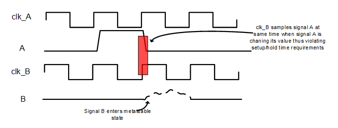
The following video provides an excellent explanation of this phenomenon and its consequences.
DVD - Lecture 8g: Clock Domain Crossing (CDC)
This lecture clip explains the concept of CDC and the resulting metastability.
Watch the first two minutes of the video. The introduction sets the stage, explaining that SoCs have multiple clock domains. The section on metastability walks through a timing diagram very similar to the image above, showing how a violation occurs. Finally, pay close attention to the summary of problems it causes: high propagation delay, high current, and—most critically—the signal being interpreted differently by different downstream logic.
The analogy often used for metastability is a ball balanced perfectly on the top of a hill. In theory, it could stay there forever. In practice, the slightest vibration will cause it to roll down one side or the other, but you cannot predict which side it will choose or exactly how long it will take to start rolling.
A metastable signal is disastrous in a digital system because our fundamental assumption is that signals are always either a '0' or a '1'. If logic that follows the metastable flip-flop samples the signal before it has settled, the entire system's behavior becomes unreliable.
3. Broader Challenges: Data Loss and Incoherence
Metastability is the root physical phenomenon, but it creates larger, system-level problems, especially when you need to transfer more than a single bit of data.
A. Data Loss
This is a particular risk when sending data from a fast clock domain to a slow clock domain. If the source domain produces new data on every clock cycle, the slower destination domain might not have enough time to see and sample the data before it's overwritten by the next value. The data is simply lost.
B. Data Incoherence (or Skew)
This happens when transferring a multi-bit value (e.g., an 8-bit data bus) across a clock domain. Even if you try to synchronize each bit individually, tiny differences in routing delays on the chip mean that some bits will arrive at their flip-flops slightly earlier or later than others.
When a CDC occurs, some bits might be captured correctly from the old value, while others are captured from the new value, and one or more might go metastable. The result is that the receiving domain captures a completely invalid, corrupted value that never existed in the source domain.
For example, if the value is changing from 0111_1111 to 1000_0000, the receiver might momentarily see 1111_1111.
The next clip in the video we just watched explains these two issues clearly.
DVD - Lecture 8g: Clock Domain Crossing (CDC)
This part of the lecture discusses the system-level problems of data loss and incoherence, and introduces the basic solution.
First, watch the brief explanation of data loss and incoherence. Then, watch the introduction to the two-flip-flop synchronizer. This is the most fundamental technique used to mitigate metastability for single-bit signals. The idea is to give the first flip-flop's output a full clock cycle to settle before it is sampled by the second flip-flop. This drastically reduces the probability of a metastable signal propagating into the rest of your design.
These issues—metastability, data loss, and data incoherence—are why CDC is a major design challenge. CDC bugs are particularly dangerous because they are often not caught by normal functional simulation (which assumes ideal clocks) and may only appear intermittently in the real hardware, making them incredibly difficult to debug.
Conclusion
In this lesson, we've explored the critical design challenge of Clock Domain Crossing. We've moved from the ideal world of single-clock systems to the realities of modern, multi-clock SoCs.
Key Takeaways:
- Clock Domain Crossing (CDC) is the passing of a signal between asynchronous clock domains.
- The primary challenge is metastability, an unpredictable state in a flip-flop caused by setup and hold time violations.
- The consequences of improper CDC handling include data loss (especially fast-to-slow domains) and data incoherence (for multi-bit buses).
- CDC creates intermittent, hard-to-reproduce bugs, making it one of the top causes of silicon failures.
- The most basic solution for single-bit CDC is a two-flop synchronizer, which provides time for a metastable signal to resolve.
Understanding and correctly handling CDC is a non-negotiable skill for any digital design engineer. While we've focused on why it's a problem today, know that there are robust solutions for every type of crossing, from simple synchronizers to handshake protocols and asynchronous FIFOs.
Having covered some advanced RTL design concepts like pipelining and CDC, we are now ready to zoom out. In the next lesson, we will begin our final module by looking at the entire journey from a design specification to a final, manufactured chip: the ASIC Design Flow.