Hello! In our last lesson, we explored how to create chorus and flanger effects by modulating the delay time of a signal. This time-domain approach, based on the Doppler effect, is effective for subtle pitch variations but can produce audible artifacts when used for larger pitch shifts. Today, we transition from the time domain to the frequency domain to analyze a much more powerful and flexible technique.
This lesson addresses the learning outcome: Analyze the phase vocoder method for time-stretching and pitch-shifting. You will learn how this classic signal processing algorithm works by separating a signal's magnitude and phase information, allowing for independent manipulation of its time and pitch characteristics. We will delve into the mathematical principles that make this possible, particularly the critical role of phase.
1. The Core Concept: Decoupling Time and Pitch
The fundamental challenge of pitch-shifting is to change a signal's frequency content without altering its duration. Conversely, time-stretching aims to change the duration without altering the pitch. A simple yet powerful insight connects these two operations:
Pitch-Shifting = Time-Stretching + Resampling
If you want to raise a signal's pitch by an octave (a factor of 2), you can first stretch its duration by a factor of 2 (keeping the pitch the same), and then play it back at double speed. The double-speed playback restores the original duration and doubles all the frequencies.
The difficult part of this process is the first step: high-quality time-stretching. A naive approach of simply cutting a signal into chunks and repeating them creates audible glitches. A slightly better method uses overlapping windows and crossfading (overlap-add), but this often results in phase cancellation artifacts, perceived as a "fluttering" sound. To solve this, we need to move to the frequency domain.
To see these concepts in action, watch the beginning of this excellent video from JentGent. It clearly demonstrates the link between time-stretching and pitch-shifting, and shows the phase-cancellation problem with naive time-domain methods.
Watch from 00:37 to 06:37. Pay close attention to: The relationship between time-stretching and pitch-shifting (00:37 - 01:40). The visualization of phase cancellation when overlapping windows of a sine wave (around 04:30). This is the central problem the phase vocoder is designed to solve.
The core of the phase vocoder method is to perform this overlap-add process not on the time-domain waveforms, but on their spectral representations, giving us precise control over phase.
2. The Phase Vocoder Framework: Analysis, Processing, Synthesis
The phase vocoder operates in three main stages, a structure you'll recognize from many signal processing systems.
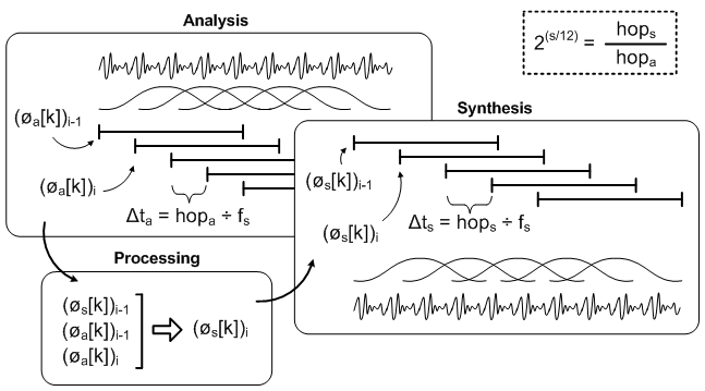
Stage 1: Analysis with the STFT
The signal is first analyzed using the Short-Time Fourier Transform (STFT). This involves:
- Breaking the input signal into short, overlapping frames. The distance between the start of consecutive frames is the hop size (
H_a). - Applying a window function (e.g., Hann window) to each frame to reduce spectral leakage.
- Calculating the Discrete Fourier Transform (DFT) for each windowed frame.
The result of the STFT is a series of complex-valued spectra. For each frame i and each frequency bin k, we get a complex number X_i[k], which we can represent by its magnitude |X_i[k]| and phase φ_i[k].
Stage 2: Processing (Modification)
This is where we manipulate the spectral data to achieve the desired effect. For time-stretching by a factor α, we need to generate α times as many frames in the output as we had in the input. A new series of frames is created by interpolating the magnitudes and, crucially, recalculating the phases of the original STFT frames. We will detail this phase calculation shortly.
Stage 3: Synthesis
The modified spectral frames are converted back to the time domain and reconstructed:
- For each modified frame, an Inverse DFT (IDFT) is computed, yielding a time-domain window.
- These windows are added together at a new synthesis hop size (
H_s) in a process called Overlap-Add. For time-stretching by factorα, we setH_s = α * H_a.
This framework is explained clearly in the following resource.
18: Phase Vocoder (part 1), C++ Real-Time Audio Programming with Bela
The Bela Platform channel provides a solid overview of the overlap-add architecture for real-time processing.
Watch the segment from 06:25 to 13:58. This part details the overlap-add process, explaining how windows are processed and stitched back together. Don't worry too much about the real-time implementation details for now; focus on the conceptual flow of windowing, processing, and overlap-adding.
3. The "Phase" in Phase Vocoder
So, how do we correctly calculate the phase for the new, synthesized frames? This is the heart of the algorithm. If we just copy or linearly interpolate the original phases, we get the same phase discontinuity problem we saw in the time domain.
The key insight, which gives the phase vocoder its name, is that the change in phase of a frequency bin from one frame to the next contains information about the true frequency of the signal component within that bin.
Let's consider a single sinusoid with true frequency . The STFT will show energy in a specific bin k with center frequency . The phase measured in bin k at frame i is . At the next frame i+1, which is H_a seconds later, the phase of the true sinusoid will have advanced by . Therefore, we expect:
The measured phase difference between frames is the heterodyne frequency, wrapped into :
\Delta\phi_i[k] = \text{principal_arg}(\phi_{i+1}[k] - \phi_i[k])
This measured phase difference is related to the true frequency deviation from the bin's center frequency:
Rearranging gives us the instantaneous frequency estimate for that bin:
This is the central mathematical principle. The phase vocoder uses the frame-to-frame phase difference to get a more accurate measurement of frequency than the FFT bin centers alone provide.
To synthesize a new frame sequence for time-stretching, we preserve this phase relationship. The phase of the new synthesis frame j is calculated by accumulating the phase increments from the previous synthesis frame:
Since is derived from the original phase differences, we are essentially "propagating" the phase correctly across the newly spaced-out frames, maintaining coherence.
This is the most critical and conceptually dense part of the lesson. The same JentGent video provides an exceptionally clear and intuitive explanation of phase propagation.
Watch the section from 09:37 to 13:44. Focus on: How the DFT bins are just an approximation of the true frequency. The core insight: the difference in phase between windows directly relates to the true frequency. The process for synthesis: interpolate the phase derivatives (differences) and then cumulatively sum them to get the new phases.
Test your understanding!
An STFT uses a sampling rate of 48000 Hz, an FFT size of 1024, and a hop size of 256 samples. You are analyzing a pure sine wave with a true frequency of 4000 Hz.
- What is the analysis hop size
H_ain seconds? - What is the frequency of bin
k=85? (Binkcorresponds to frequencyk * fs / N). - What is the expected phase advance for the true frequency between two consecutive frames?
- What is the expected phase advance for the bin center frequency between two frames?
- What is the expected phase difference,
Δφ[85], that you would measure in bin 85?
Show answer
H_a = 256 samples / 48000 samples/sec = 0.00533seconds.- Frequency of bin 85:
f_85 = 85 * 48000 / 1024 = 3984.375Hz. In radians/sec,ω_85 = 2π * f_85 ≈ 25034.4rad/s. - The true frequency is
f = 4000Hz, orω = 2π * 4000 ≈ 25132.7rad/s. The expected phase advance isω * H_a ≈ 25132.7 * 0.00533 ≈ 134.0radians. - The expected phase advance for the bin center is
ω_85 * H_a ≈ 25034.4 * 0.00533 ≈ 133.4radians. - The measured phase difference
Δφ[85]is the heterodyne phase advance:(ω - ω_85) * H_a ≈ (25132.7 - 25034.4) * 0.00533 ≈ 0.524radians. This small phase difference correctly encodes the deviation of the true frequency from the bin center.
4. From Time-Stretching to Pitch-Shifting
With a high-quality time-stretching algorithm in hand, pitch-shifting becomes straightforward.
Method 1: Time-Stretch and Resample
As discussed, you time-stretch by a factor α and then resample the output by the same factor (i.e., change the playback speed). This is the "classic" phase vocoder pitch-shifter. Its main drawback is that the computational cost can depend on the scaling factor.
An Open-Source Phase Vocoder with Some Novel ...
For a formal description of these algorithms, we'll consult the paper 'An Open-Source Phase Vocoder'. It includes clear, step-by-step algorithms and pseudocode.
Read the following sections: Section 2.2 'Processing and Resynthesis': Understand the high-level distinction between time-stretching and pitch-shifting. Algorithm for time-stretching: Review the step-by-step process at the bottom of page 10. Algorithm for pitch-shifting: Review the algorithm on page 11. Note that it involves the extra step of 'interpolation', which is their term for resampling. Appendix A.4: Skim the pseudocode for pitch-shifting. Notice the distinct blocks for 'phase unwrapping' (calculating phase differences), 'process' (accumulating new phase), and 'resynthesis' (including interpolation).
Method 2: Direct Frequency-Domain Shifting
A more advanced and efficient method, developed later, performs the pitch modification directly in the frequency domain. This avoids the separate resampling step. A particularly elegant approach was proposed by Laroche and Dolson.
new phase-vocoder techniques for pitch-shifting, ...
This 1999 paper by Laroche and Dolson was influential in improving phase vocoder quality and efficiency. It introduces a method that directly manipulates the spectrum, providing the historical context and deeper insight you appreciate.
Please read these sections from 'NEW PHASE-VOCODER TECHNIQUES...'. Section 1 & 2: Understand the critique of the standard time-stretch/resample method. Section 3.1 'Underlying idea': Grasp the core concept: identify peaks in the spectrum and physically translate them to new frequency locations. Section 3.5 'Adjusting the phases': This is the key. Notice how phase coherence is maintained not by unwrapping and integration, but by a simple complex multiplication (rotation) exp(j Δω R), where Δω is the frequency shift and R is the hop size. This is a much simpler and more robust way to handle phase. Section 4 'Discussion and Conclusion': Summarize the advantages: fixed computational cost and higher quality due to implicit 'Identity Phase-Locking'.
This peak-based method improves quality by preserving the phase relationships within a spectral peak ("phase locking"), which reduces the "phasiness" artifact common in simpler vocoders. It also elegantly handles phase propagation through a simple rotation, a computationally efficient and robust alternative to the standard phase unwrapping and integration procedure.
5. Handling Transients
A final, crucial consideration is the handling of transients—sharp, percussive sounds like drum hits or plucked strings. The phase vocoder's underlying assumption is that the signal is composed of slowly-varying sinusoids. This assumption breaks down for transients, whose energy is tightly localized in time, not frequency. Applying the phase propagation logic to transients results in them being "smeared" in time, losing their impact.
A common and effective solution is to implement a transient detector. When a transient is detected in a frame:
- The phase propagation logic is bypassed.
- The original phase information from the corresponding analysis frame is used directly.
- This preserves the temporal shape of the transient at the cost of some pitch inaccuracy, which is perceptually far more acceptable.
The JentGent video you watched earlier demonstrates this technique and its impressive results in the final part of its implementation.
Conclusion
You have now analyzed the phase vocoder, a cornerstone of modern audio signal processing. You've seen how it moves beyond the limitations of time-domain methods by operating in the frequency domain, enabling independent and high-quality control over a signal's pitch and duration.
Key Takeaways:
- The phase vocoder works via an analysis-processing-synthesis pipeline based on the STFT and overlap-add reconstruction.
- The relationship Pitch Shift = Time Stretch + Resample provides the conceptual basis for one method of phase vocoding.
- The central principle is maintaining phase coherence. This is achieved by calculating the instantaneous frequency from the frame-to-frame phase difference (
Δφ) and using it to propagate phase correctly in the synthesized signal. - Advanced methods can shift pitch directly in the frequency domain by translating spectral peaks and applying a simple phase rotation, improving both quality and efficiency.
- Transients require special handling (e.g., phase reset) to avoid temporal "smearing," as they violate the vocoder's underlying sinusoidal model.
Preview of the Next Lesson:
This lesson on the phase vocoder completes our survey of fundamental audio effects. You now have a toolkit that includes filtering, equalization, delay-based effects, and spectral manipulation. In the final lesson of this capstone module, "Integrate spectral analysis, equalization, and a chosen audio effect into a single processing chain," you will bring these components together. You'll design and conceptualize a complete, real-time audio effects processor, combining the techniques you've learned throughout this course into a single, cohesive system.