Hello! Welcome back to your Embedded Interview Preparation Bootcamp.
In our last lesson, we architected a robust bootloader and OTA update system, focusing on ensuring the system's integrity and recoverability. We designed for resilience against update failures. Today, we'll expand on this theme of system reliability by diving into the formal process of ensuring safety, even when hardware or software malfunctions during operation.
Your learning outcome for this lesson is to: Explain key concepts of functional safety (ISO 26262), including ASIL levels and fault tolerance patterns like dual-core lockstep.
This topic is a cornerstone of modern automotive engineering and a frequent subject in system design interviews at top semiconductor companies. Demonstrating a solid grasp of functional safety shows that you can think about system reliability and failure mitigation at a professional, certifiable level—a non-negotiable skill for anyone working on silicon that goes into cars.
We will cover:
- The "why" behind functional safety and the role of the ISO 26262 standard.
- How risk is quantified using Automotive Safety Integrity Levels (ASILs).
- Architectural patterns, particularly dual-core lockstep, used to achieve the highest levels of safety.
1. The Need for Functional Safety: ISO 26262
As electronic systems in vehicles have grown from simple engine controllers to complex advanced driver-assistance systems (ADAS) and autonomous driving platforms, the potential for software or hardware faults to cause harm has increased dramatically. Functional safety is the discipline of ensuring that these systems do not pose an unreasonable risk to people.
The guiding standard for this in the automotive world is ISO 26262. It provides a comprehensive framework and a V-model development process to manage safety throughout the entire product lifecycle.

To understand the motivation and core principles, let's watch a segment from a presentation on the topic.
Functional Safety with ISO 26262 - Principles and Practice
This video, 'Functional Safety with ISO 26262 - Principles and Practice' from Vector Consulting Services, provides an excellent introduction to why the standard exists and its fundamental concepts.
Please watch the following segments: The Challenge of Complexity (06:04 - 09:30): This explains the core problem ISO 26262 aims to solve—the gap between the exponential growth in E/E system complexity and the ability of engineering teams to manage it. Part 11 for Semiconductors (19:30 - 20:30): Pay close attention to this part. It highlights that the standard has a specific guide (Part 11) for applying functional safety to complex semiconductors, which is directly relevant to roles at companies like NXP, Qualcomm, and NVIDIA.
ISO 26262 distinguishes between two fundamental types of failures:
- Systematic Failures: These are deterministic faults introduced during development (e.g., a software bug, a design flaw in the hardware). They can be eliminated by improving the development process. The V-model, with its rigorous requirements, traceability, and verification, is designed to prevent systematic failures.
- Random Hardware Failures: These are unpredictable failures that occur during the lifetime of a device (e.g., a bit flip from a cosmic ray, a transistor wearing out). You cannot prevent them entirely, but you can design the system to detect them and react in a safe manner.
Our focus for the rest of this lesson will be on the architectural patterns used to handle these random hardware failures.
2. Quantifying Risk: Automotive Safety Integrity Levels (ASIL)
Not all functions in a car have the same safety implications. A malfunctioning radio is an annoyance; a malfunctioning airbag is a disaster. ISO 26262 introduces Automotive Safety Integrity Levels (ASILs) to classify the level of risk associated with a function's failure and to define the necessary rigor to ensure its safety.
An ASIL is determined through a process called Hazard Analysis and Risk Assessment (HARA), which evaluates three factors for a given hazardous event:
- Severity (S): How serious are the potential injuries? (S0: No injury to S3: Life-threatening)
- Exposure (E): How often is the vehicle in a situation where the fault could occur? (E0: Incredibly unlikely to E4: High probability)
- Controllability (C): How likely is it that the driver can act to prevent the injury? (C0: Controllable in general to C3: Difficult or impossible to control)
These three factors are combined in a set of tables defined by the standard to determine the final ASIL, which ranges from QM (Quality Management, for non-safety-critical functions) to ASIL D (the most critical).
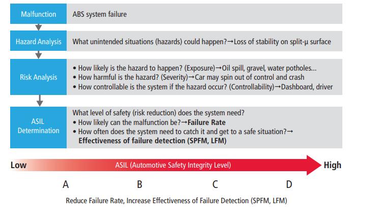
Let's watch a clear walkthrough of this process with a practical example.
Functional Safety with ISO 26262 - Principles and Practice
Returning to the Vector Consulting video, this segment provides a concrete explanation of ASIL calculation.
Watch the section ASIL Calculation and Example (23:35 - 29:46). Focus on how the S, E, and C parameters for a braking function are used with a lookup table to derive an ASIL rating and its corresponding Safety Goal.
The key takeaway is that a higher ASIL (like ASIL C or D) imposes much stricter requirements on the system, demanding higher diagnostic coverage and a lower probability of dangerous failures.
3. Achieving High Integrity: Fault Tolerance Patterns
How do you build a system that meets the stringent requirements of ASIL D, where a single random hardware fault cannot lead to a violation of the safety goal? The answer is fault tolerance through redundancy.
Fail-Safe vs. Fail-Operational
First, we need to define how the system should react to a fault.
- Fail-Safe: The system transitions to a safe state where it can no longer cause harm. For many functions (like cruise control), simply shutting it off is a safe state.
- Fail-Operational: The system continues to provide its function, perhaps in a degraded state, even after a fault. This is essential for functions like steer-by-wire or brake-by-wire, especially in autonomous vehicles where there may not be a driver to take over.
Achieving fail-operational behavior almost always requires hardware redundancy. For an interview at a semiconductor company, the most important pattern to understand is dual-core lockstep.
Architectural Approach: Dual-Core Lockstep
Instead of using two separate microcontrollers and complex software to compare their outputs, a lockstep MCU integrates this redundancy directly into the silicon.
Safety Integrated Hardware Solutions to support ASIL D Applications
This whitepaper from NXP, 'Safety Integrated Hardware Solutions to support ASIL D Applications', is an excellent resource that directly compares system architectures for achieving ASIL D.
Please read the section 'ASIL-D Solutions and the Influence of Safety Architecture', starting on page 4. Pay close attention to the comparison between the first approach (two separate MCUs) and the second approach (a multicore MCU in lock-step mode). Understand the trade-offs discussed: system complexity, PCB space, reliability, and software development effort.
As the paper explains, a lockstep architecture involves:
- Duplicate Cores: Two CPU cores execute the exact same instruction stream.
- Delayed Execution: One core's execution is slightly delayed (by a few clock cycles).
- Comparator Logic: A hardware comparator checks the outputs of both cores on every single clock cycle.
- Fault Detection: If there is any mismatch—caused by a random hardware fault in one of the cores—the comparator immediately triggers a fault signal. The system can then enter a safe state.
This provides near-instantaneous detection of any random hardware fault in the CPU core. But a modern lockstep MCU does more than just duplicate the cores.
Safety Integrated Hardware Solutions to support ASIL D Applications
Let's continue with the NXP paper to see what other parts of the MCU are made redundant to provide comprehensive diagnostic coverage.
Read the following sections: 'The Freescale hardware system concept...' (page 5): Note the list of other key hardware blocks that are replicated in the sphere of replication: crossbar, memory protection units, interrupt controller, etc. This is crucial detail for an interview. The table on page 7: This table summarizes how different hardware elements (Processing Unit, RAM, Power Supply) are protected by specific safety mechanisms (Dual-core lock step, ECC, Voltage control) and the typical diagnostic coverage achieved. This is a perfect summary of practical safety mechanisms.
By integrating redundancy for the cores, bus interconnects, and memory controllers, a lockstep MCU can achieve extremely high diagnostic coverage (>99%) for single-point faults, making it a cornerstone for building ASIL D systems like electric power steering (EPS), braking, and airbag controllers.
Conclusion
Today, we've explored the foundational concepts of automotive functional safety, a critical domain for embedded systems engineering in safety-conscious industries. You are now equipped to discuss this topic with the depth and practical knowledge expected in a senior-level interview.
Key Takeaways:
- ISO 26262 provides the framework for managing risk from E/E system failures. It addresses both systematic (process) and random (hardware) faults.
- ASILs (A-D) are risk levels determined by analyzing the Severity, Exposure, and Controllability of a potential hazard. The ASIL dictates the required engineering rigor.
- Fault Tolerance is key to handling random hardware failures. For high-ASIL systems, this often means hardware redundancy.
- Dual-Core Lockstep is a powerful architectural pattern that integrates redundancy directly into the silicon. It duplicates not just the CPU cores but other critical logic, providing extremely high diagnostic coverage and forming the basis for many ASIL D compliant systems.
- Discussing Trade-offs is crucial. Be prepared to compare a lockstep MCU approach with a dual-MCU system, weighing factors like BOM cost, PCB area, software complexity, and overall system reliability.
Preview of the Next Lesson:
In our last session on system design, we will bridge the gap between high-level architecture and low-level software implementation. Our next topic will be: Design a layered device driver architecture that separates protocol logic from physical bus access. This will focus on creating portable, maintainable, and testable driver code—a skill essential for any experienced embedded engineer.